Understanding Slenderness in Steel and Aluminum Members
Bigger does not always mean stronger. In steel and aluminum design, geometry often controls performance more than material strength.
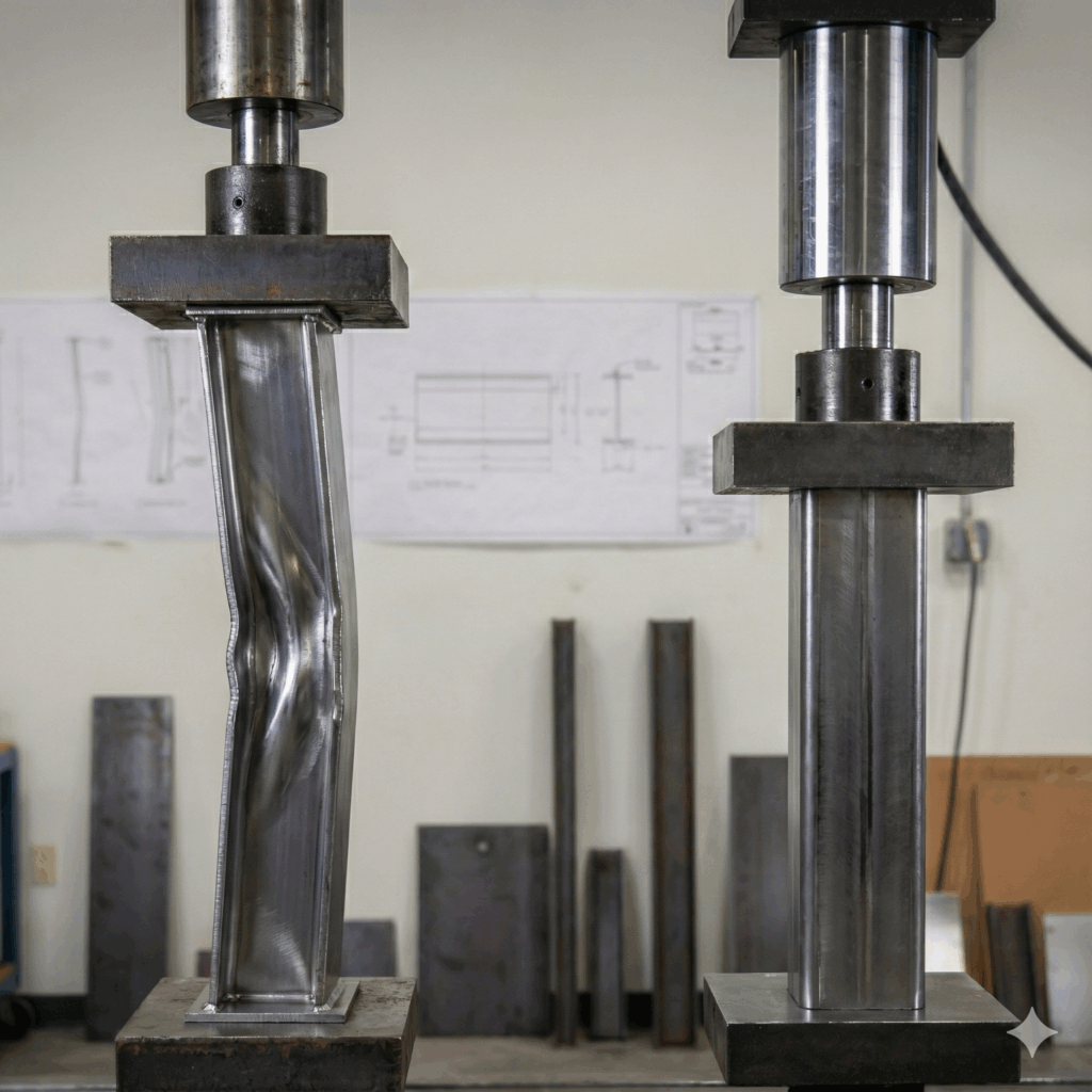
This is where slenderness matters. Slenderness describes how thin a member, or its walls, are compared to its size. Highly slender sections are more likely to buckle and may never reach their full capacity.
This article helps clarify the concept of slenderness by looking at section shape, wall thickness, how it is evaluated in practice, and how design codes account for it in steel and aluminum members.
What is Slenderness?
A simple way to think about slenderness is this:
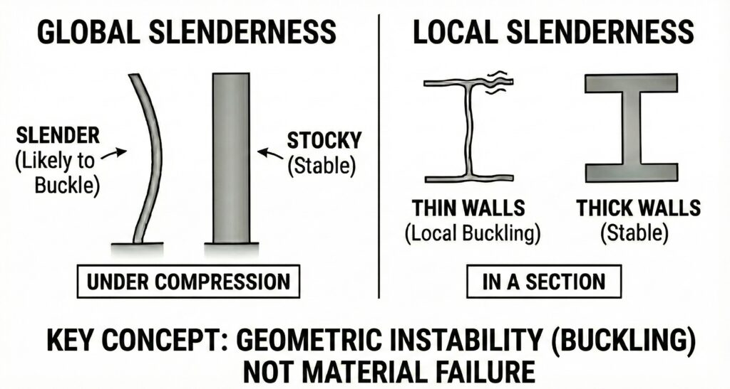
• Long and thin members are more likely to buckle than short, stocky ones.
• Wide and thin walls are more likely to buckle than narrow, thick ones
In both cases, the issue is instability, not material failure. A slender element can buckle or deform before the steel or aluminum reaches its full strength.
Slenderness applies at two levels:
• Global slenderness, which affects the entire member, such as a column or post under compression.
• Local slenderness, which affects the individual walls of a section, such as flanges, webs, or tube walls.
This is why a member can look large and strong, yet still have a limited capacity. When geometry makes a member too slender, it will buckle before the material can reach its full strength.
Understanding slenderness means understanding that strength is not just about how much material you use, but how that material is distributed.
Closed vs Open Sections
Section shape plays a major role in how slenderness affects member performance. In practice, this often comes down to the choice between closed and open sections.
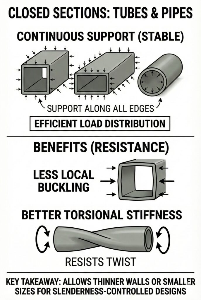
• Closed Sections
Closed sections include rectangular tubes, square tubes, and pipes. Their continuous geometry provides support along all edges of each wall, which improves stability and load distribution.
As a result, closed sections generally:
• Are less sensitive to local buckling for a given wall thickness
• Provide better torsional stiffness
• Perform efficiently in compression and bending
For slenderness-controlled designs, closed sections often allow thinner walls or smaller overall sizes while still achieving the required strength.
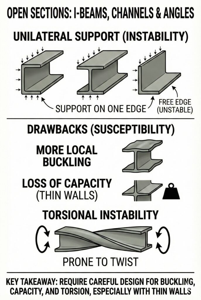
• Open Sections
Open sections include channels, I-beams, and angles. These shapes are made of flat elements (flanges and webs) that are often supported on only one edge. Open sections are widely used due to their fabrication simplicity, efficient one-axis bending performance, and compatibility with typical framing details.
Because of this geometry, open sections are more prone to:
• Local buckling of thin flanges or webs
• Loss of capacity as wall thickness decreases
• Torsional instability
When properly sized and detailed, open sections can perform very well, but they typically require greater attention to wall thickness and bracing when slenderness is a concern.
How to Calculate Slenderness?
Building codes use the effective slenderness ratio as a critical checkpoint for your design. Its primary job is to check stability against a standard limit. For example, AISC Section E2 advises a maximum ratio of 200 for compression members. If your number exceeds this, it is a clear warning sign that the column is likely too unstable. Even if within limits, this number acts as a modifier: it determines if you can use the material’s full strength or if you must trigger additional calculation steps to apply a strength penalty. Finally, consistent with AISC and the Aluminum Design Manual (ADM), you can also calculate local stability to verify that the individual walls are robust enough for the load.
Here is a brief breakdown of these calculations; however, please always verify your specific case with a qualified engineer.
Global Slenderness
The primary calculation looks at the entire member to see if it will bow out under load. The formula used in almost all building codes is:
– K (Effective Length): A factor representing stability (e.g., how the ends are fixed).
– L (Length): The actual height of the column.
– r (Radius of Gyration): This is the most important variable for choosing a shape, as it measures how effectively material is distributed to resist buckling. Closed sections generally offer a higher, more uniform r than Open sections of the same weight, making them more efficient for compression.
Local Slenderness
You can also verify the “Size vs. Thickness” of the cross-section walls. This ensures the steel or aluminum doesn’t crumple locally before the column reaches its full potential.
In practice, this is often pre-calculated by the manufacturer or listed in standard property tables, but the underlying check is the Width-to-Thickness Ratio:
– b: The width of the flat element (flange or web).
– t: The thickness of the wall.
The “Buckling Cliff”: How Length Drives Slenderness
The Real-World Impact: Take a standard steel tube as an example:
• At 10 feet: The slenderness ratio is low. The column is stable and fails only if you physically crush the steel.
• At 15 feet: You added just 5 feet, but that extra length pushed the slenderness ratio higher, right off the “cliff.”
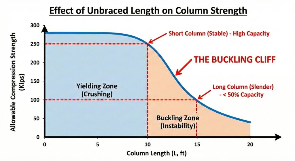
Chart and values shown are for illustration only and do not represent a specific design case.
The Result? That 50% increase in length (and slenderness) can reduce the total strength by over 50%. This is why you can never assume a column that worked on a short span will work on a longer one. As slenderness increases, the physics change from simple crushing to instability, and gravity wins easily.
This article has outlined the fundamental principles of slenderness for both steel and aluminum members, but it is critical to verify that your calculated ratios comply with the latest codes and project standards. When dealing with long unbraced lengths, high axial loads, or sections approaching the slender limit, always consult the Engineer of Record for final approval.
For more detailed information and professional support on your future projects, don’t hesitate to contact us. If you have any questions or want to learn more about our services, simply get in touch. Click the buttons below to get started!
For more detailed information and guidance on handling your future design projects, check out our online design calculators, contact us for site-specific projects, or reach out to us with your inquiries.
Last Update: January 16, 2026
Related Knowledge Base Posts -
No related posts found !