FREQUENTLY ASKED QUESTIONS
Our FAQ includes common company questions, online plan & site-specific job ordering.
Also Visit Our Knowledge Base
Search our entire Knowledge Base, a library full of engineering & code related articles.
Try Our Experimenal AI Chat
Switch to Article Mode
Models
Ordering – Payments – Tokens – Delivery – Subscriptions & Memberships 27
Understanding The Material Cost Saving of Using An Engineering Express Calculator
Tell us how can we improve this post?
FAQ Is the 7th Edition Florida Building Code still valid? That’s what it says on my plan.
If the controlling permit for your project is dated prior to Jan 1, 2024, then the 7th Edition Florida Building Code is still valid. Otherwise, you will need to place an order for an updated version of the plan
(please visit EngineeringExpress.com/store/ to start your search
(We recommend beginning with the brand needed if known or project number you have on your outdated plan).
Tell us how can we improve this post?
FAQ How can I pay for something custom that’s not a store product or something quoted?
There are occasions where we may customize something for you that doesn’t exactly fit a store product but isn’t something we quote. For this reason we have this product to allow you to pre-pay for a custom service as instructed by our project coordination team:
https://www.engineeringexpress.com/product/single-tokens-pre-purchase/
NOTE: Payments made through this system are NOT REFUNDABLE, so please be sure with us that this is the correct payment method before submitting.
Payments for professional services that were invoiced are made through our secure server at https://www.engineeringexpress.com/pay/
Tell us how can we improve this post?
How To Use Performance Evaluations – TER’s – Calculator Reports Purchased From Engineering Express
READ BELOW BEFORE USING NON SITE-SPECIFIC PERFORMANCE EVALUATIONS
FROM ENGINEERING EXPRESS FOR YOUR PROJECT
General Information About Non Site-Specific Plans:
Certified Performance Evaluations (also referred to as Master Plans, Technical Evaluation Reports (TER’s), Generic or Non Site-Specific Plans) you receive contain a physical or digitally certified engineer seal. They are intended to be used to assist in obtaining a building permit and in constructing the component conveyed in the plan.
In all cases using a non-site specific plan, additional documentation is required to serve as approval of use of the purchased document for the intended location.
The design professional providing the site-specific approval for use then becomes the responsible party for their use at that location. This additional documentation is provided by others and not part of the purchase of generic plans or Technical Evaluation Reports (TER’s) from us.
At no time is construction to be performed without the review and approval by another party of the documents purchased regarding the applicability, limitations of use, and proper selection of plan detail options for the intended installation.
In all cases, completed work shall be inspected and approved by others before approval for use including but not limited to the municipality having jurisdiction, architect and/or engineer of record, and permitting contractor which is not our responsibility or part of this purchase.
The documents you purchase from us unless otherwise stated are for sole approval of a pre-engineered, non-site-specific building component subject to the stated limitations of use only and are NOT intended to serve as approval for the construction of any design or installation.
ALSO, AT NO TIME IS ANY PHOTOCOPY OR UNSEALED DOCUMENT TO BE USED OF PLANS FOR PERMIT UNDER ANY CIRCUMSTANCES. BUILDING CODES REQUIRE AN ORIGINAL, CERTIFIED DOCUMENT FOR EACH PERMIT TO BE VALID FOR USE.
Using Certified Performance Evaluations, TER’s & Other Reports
The Generic Plans & Technical Evaluation Reports (TER) we provide are structural performance evaluations of the subject building component and do not contain a site-specific address. The certification of those documents approves the limitations of use as stated, NOT that the building component can be used at a specific location. That is the responsibility of others as described herein.
THIS ALSO INCLUDES THE USE OF PERFORMANCE EVALUATIONS SUCH AS MIAMI DADE NOA’S, FLORIDA PRODUCT APPROVALS, TEXAS TDI EVALUATIONS, & ICC EVALUATION REPORTS WHICH FOLLOW THE SAME REGULATIONS AS OUR GENERAL PLANS & TER’S.
The design professional or user of the original, certified documents (never photocopies) shall carefully review each detail for applicability to their site-specific condition and gain approval of use for their application by others.
Engineering Express remains available for questions via email, online chat, or phone for questions or clarifications of the information within the purchased document and as contained herein which may result in additional engineering consultation fees.
Site-specific review and approval and customized & site-specific design plan services are also available which can be performed by this office or another licensed professional.
Using Certified Design Calculator Reports With Addresses Generated By Engineering Express
Printouts from online calculators may come with a site-specific address. It is understood and agreed that the address, as well as all inputted information, is provided by the purchaser at the time of purchase. By agreeing to purchase the document, you understand and affirm that we have not been contracted to a site-specific study, field investigation, or review design plans by others to provide the result you purchased.
The site-specific address you provide serves to bind the document to your permit as is required by code and does not constitute that a site-specific or field review has been performed by this firm to authorize their use.
The documents also contain information explaining this, as well as the fact that the certified results are to be reviewed by a design professional along with other required construction documents to obtain a permit for construction and use.
The information provided in the purchased document shall at all times be reviewed and approved by others for applicability and accuracy of the intended use prior to permitting and construction.
This office is solely providing a result based on the information you provide to us, that you have affirmed to us is accurate at the time of purchase, and that you have had an opportunity to consult with us prior to use if at all in doubt or have any questions about the use of the document we provided. Information regarding contacting us is provided below.
About Digitally Signed Documents
Digitally signed documents typically contain a disclaimer box limiting the use of the document to a specific contractor with a geographic zip code limitation and approved date range to apply for an electronic permit. Digitally signed documents also contain encryption to verify the authenticity of the document which shall be verified by electronic means by others before use.
Digitally signed documents must remain digital and become invalid for use once printed. Scanned copies of printed digitally sealed plans are no longer considered digital and are invalid for use.
The zip code provided in the disclaimer is provided solely to limit repeated use of the document and is not intended to serve as approval that the purchased document is valid for use within that zip code or any site-specific address contained within.
Signed documents may also contain a building floor elevation to which the use is limited to which is requested and provided solely to limit misuse of the signed document.
Certification at a specific address and building floor is the responsibility of others as described herein.
The date limitation is intended to limit the amount of time the permittee has to submit the document with the electronic application for permit. The document is valid for use within the limitations and building codes provided on the purchased document for submittal for permit during the approved date range only.
More information about digitally signed documents can be found by clicking here.
About Physical Printed ‘Hardcopies’
Documents that are physically printed (also known as hard copies) are signed and sealed with an embossed or ‘wet’ ink seal by the certifying design professional.
For these documents to be valid for use, the ORIGINAL document must be presented to the approving municipality. PHOTOCOPIES OF PRINTED DOCUMENTS ARE NOT CONSIDERED SIGNED AND SEALED AND ARE NOT VALID FOR USE.
This firm is not responsible for the use of any photocopied document of our signed and sealed work.
Additionally, markings or alterations to original signed and sealed documents invalidate our certification and require additional review prior to use.
Each signed and sealed document contains information on how to obtain an originally signed and sealed version.
More information about physically signed documents can be found by clicking here.
About Generic Documents Purchased For Building Components Attached To Structures
Documents purchased for host-attached building components (such as overhangs, wall-mounted signs, and rooftop mechanical equipment) DO NOT certify the building component for use on any specific project.
Each of these performance evaluations requires another design professional to review and approve the document for the intended site-specific application including the integrity of the host structure to withstand the additional forces placed by the building component at the time of the worst-case design condition (such as during a hurricane, snowstorm, earthquake, maximum occupancy load, etc).
THE DOCUMENTS PURCHASED THROUGH THE ONLINE PLAN STORE OR DOWNLOADED FROM A STATE EVALUATION SITE (SUCH AS MIAMI DADE NOA’S OR FL PRODUCT APROVALS) DO NOT DO THIS. ADDITIONAL STEPS MUST BE TAKEN PRIOR TO PERMITTING AND CONSTRUCTION.
The purchased documents solely state the performance limitation of the building component to the loads and design wind/snow/seismic/forces listed within the evaluation.
The actual code-minimum design forces for your site-specific project may be HIGHER than the limitations of the purchased document which shall be determined, reviewed, and approved by others and not part of our certification or your purchase.
The determination of the applicability of the use of the purchased documents is the sole responsibility of others and not purchased or included in the document you obtain from us.
Engineering Express can provide a quotation for these additional site-specific services.
Click Here to apply for access to our quoting system to submit a site-specific design request.
About Generic Documents Purchased For Freestanding Building Components
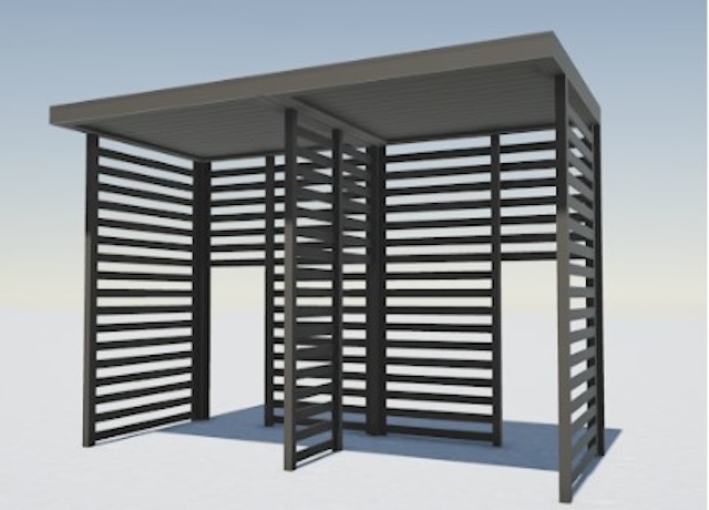
Documents purchased for freestanding building components (such as fences, freestanding pergolas, A/C and generator pads, and ground-mounted signs) contain limitations of their use and may contain equivalent design information (such as wind, snow, geotechnical, and seismic equivalent values).
These documents DO NOT approve the use of the building component for YOUR APPLICATION. The documents we provide state that IF your application meets the listed limitations of use, the building component can withstand the imposed code-minimum design forces and limitations as stated on the respective plan.
The determination of the applicability of the use of the purchased documents is the sole responsibility of others and not purchased or included in the document you obtain from us.
Engineering Express can provide a quotation for these additional site-specific services.
Click Here to apply for access to our quoting system to submit a site-specific design request.
Other:
While any licensed professional can provide the site-specific information required for use with the purchased documents as described herein, this office welcomes the opportunity to quote these additional services for other businesses.
Click Here to apply for access to our quoting system to submit a site-specific design request.
Certified documents are only valid for the state, building code, and limitations of use listed in the original, certified document. For use in states and building codes other than listed, contact the office for further evaluation which may require alterations to the performance limitations or review and certification by a licensed professional in the state requested.
Please note that while homeowners may purchase documents from our plan store, we do not perform any consultation services directly with homeowners.
If you are a homeowner and purchased certified documents from our plan store, please have your contractor contact us, or work with a local licensed professional to complete your application for permit which shall include their approval for use of your purchased documents for your specific project.
We are not responsible for any installation deficiencies that occur from the misuse of any certified document purchased from us. Any deviations from the specifications in our plans, alterations, or markings to our certified documents or use without consulting a design professional is strictly prohibited and INVALIDATE OUR CERTIFICATION.
Use of the purchased documents indemnifies & saves harmless the engineer & firm for all cost & damages including legal & appellate fees resulting from deviations of the certified plan as well as material fabrication, system erection, & construction practices beyond which is called for by local, state, & federal codes and standards of care.
The determination of the applicability of the use of the purchased documents is the sole responsibility of others and is not included in the document you obtain from us.
Engineering Express can provide a quotation for these additional site-specific services. Click Here to apply for access to our quoting system to submit a site-specific design request.
Contact this office with any questions or to request a design consultation which is required prior to permitting and construction to ensure proper use of these documents and a safe, code-compliant design.
Tell us how can we improve this post?
FAQ How can you leave my order outside in one of your office pickup boxes?
Pickups have been discontinued from all of our Office Locations. Not to worry, we have free local shipping for minimum fee orders and are happy to work with any of our repeat clients on ways to avoid shipping fees for small orders.
Contact us or chat with us online to discuss your express delivery needs on any project or online order.
Tell us how can we improve this post?
FAQ I need help finding a tie down detail for permit
Tie-down details are incorporated into Technical Evaluation Reports (TERs) which are cataloged by model number for manufacturers such as Trane, Carrier, Daikin, Samsung, Mitsubishi, and others.
You can search for tie down details by model number or TER number/name on our mechanical page.
You can also visit EngineeringExpress.com/store to search for the product you need (Begin by the brand needed then select the type of unit).
NOTE: Engineering Express only provides tie-down details for models we are contracted for by the product manufacturers. If you don’t see what you need, you will need to contact the product distributor to locate the tie down detail by their respective engineer.
Tell us how can we improve this post?
FAQ How do I know if a payment went through for my online order?
You will get an email to confirm we have received your request once the payment has been approved
Tell us how can we improve this post?
FAQ How can clients in the South Florida area save money on shipping fees on project hardcopy deliveries?
If you are a frequent buyer in the South Florida area, consider merging your orders into a single purchase over $100.00 (Digital and/or hard copies) to qualify for free local shipping (Miami Dade, Broward & Palm Beach counties, Florida)
Tell us how can we improve this post?
FAQ I need to create an NOA / product approval for my product. What’s the process?
See Our Guide To Obtaining The Right Product Approval For You
Summary Of The Guide
Start by reading our articles about product approvals by Clicking Here. You’ll learn when they’re really needed, what information we need, how they help, and much more.
> In short, products ‘inside the rule‘ require product approval in Florida.
> This is done by a combination of testing & rational analysis as determined by code.
> Most products such as windows, doors, and roofing require extensive testing. From there, the tests can be uploaded to the State of Florida or Evaluated by an engineer. Product Evaluations allow variations such as alternate sizes, substrates, and anchoring.
> Prior to testing, a qualified firm should be retained to establish a test protocol to maximize the use of the test results. That firm needs to be independent of the lab conducting the testing.
> With testing complete, the evaluating engineer would consult with you on the best format to display the evaluation.
> For Florida Product Approvals, prior to submitting to the state, a Validator and Quality Assurance entity needs to be retained to provide the 3rd party assurance that the evaluation is performed per code and the product meets the tested parameters over time.
> After the Florida Approval is granted, the document registration number can be used for permit in Florida if the installation matches the intent of the evaluation report. Typically a local design professional (architect or engineer) is retained to establish the design criteria of the local installation and ‘approve’ the approval for use at that location/opening. Modifications may be permitted if performed within the guidelines of the building code, referenced standards, and the limitations of the evaluation.
You can search Florida & Miami Dade Product Approvals for similar examples of your product for consideration by clicking here.
When you’re ready for Engineering Express to help & have the information gathered in the articles, visit EngineeringExpress.com/Quote to apply for access & request a quote for your product evaluation.
We will contact you shortly thereafter to discuss your needs & detail & how our national certifications can help.
USEFUL ARTICLES
For guidance with your next project, explore our Plans, Calculators, Knowledge Base,
or contact us directly for site-specific support
Visit Our Plan Store
Online Design Calculators
Visit Our Knowledge Base
Site specific project request
Chat with a Designer
Chat with a Designer
Site specific project request
Visit Our Plan Store
Online Design Calculators
Tell us how can we improve this post?
FAQ I have a different brand product than the one you specify but it’s similar. How can I get mine certified for permit?
This would require the project to be site specific.
Please visit EngineeringExpress.com/ExpressPass to apply for access to request a quote for a site-specific project.
Click ‘apply for access’, fill the form and in the description box, please give us an idea of the project you are looking for. After submitting a team leader will contact you back with the following steps.
(This process can’t be done by homeowners. We recommend finding a contractor to assist or another local engineer).
Tell us how can we improve this post?
FAQ I received a hardcopy (printed) plan and need a digitally signed-sealed file. What do I do?
You will need to place a new order in our online plan store for the same plan but select ‘digitally sealed file’ under the ‘plan format’ option & re-pay for the plan.
If you can return the physical plan we will provide Tokens as credits for additional orders. See our Refund policy for more.
Tell us how can we improve this post?
FAQ I’d like to use an EFT (electronic funds transfer) or ACH instead of a credit card. Can you help with that?
See our Pay Page or contact our office for more information.
Tell us how can we improve this post?
FAQ I placed an order for pickup that now needs to be shipped. What do I do?
Engineering Express discontinued pickup from all of our Office Locations. That option has been removed from our online store in case you are looking for it.
Not to worry, we have free local shipping for minimum fee orders and are happy to work with any of our repeat clients on ways to avoid shipping fees for small orders.
Contact us or chat with us online to discuss your express delivery needs on any project or online order.
Tell us how can we improve this post?
FAQ I made a mistake on the zip code of an online digital order. What do I do?
This can only be done if the order has not been processed. Please contact our office for further assistance or use our Live Chat feature.
Tell us how can we improve this post?
FAQ How can I cancel an online order?
This can only be done if the order has not been processed or shipped. Please contact our office for further assistance or use our Live Chat feature.
Tell us how can we improve this post?
FAQ I ordered a project through E-Tempest. What’s the process for receiving a digitally signed-sealed file?
Engineering Express provides engineering review & certification of orders placed through E-Tempest shutter software. If you ordered the digitally signed and sealed file from E-Tempest, it will be emailed to you as a PDF attachment. If you requested Hard copies but need a digitally signed – sealed file, please contact E-Tempest directly.
Tell us how can we improve this post?
FAQ Can I get a discount on volume plan store orders?
Engineering Express has developed an efficient system for volume discounts. Discounts are offered by purchasing Tokens in bulk. This allows volume orders to be spread out over time & products, and also avoids license fee charges.
Visit EngineeringExpress.com/Tokens for more information about our token system and bulk discounts.
Tell us how can we improve this post?
FAQ I’m looking for a model not shown on the chart in a Technical Evaluation Report (TER). What do I do?
Engineering Express would love to have every model unit of an A/C or generator pre-engineered. We can only engineer what we’re hired to do by the manufacturer so letting them know is always an option.
If you are a contractor & in need of our help right away, you would need to order a site-specific design so we can process 1 model for 1 address efficiently & inexpensively. Visit EngineeringExpress.com/ExpressPass, to apply for an account & request a quote for a site-specific project.
Click at apply for access, fill the form and in the description box, please give us an idea of the project you are looking for, after submitting a team leader will contact you back with the following steps.
(This process can’t be done by homeowners. We recommend hiring a contractor or calling the manufacturer. We simply cannot handle the volume of homeowner requests with the price point needed & volume of information we need to obtain).
Tell us how can we improve this post?
FAQ How can I clarify my account status with Engineering Express?
If you have reason to believe your account is not in good standing, or if a designer tells you they cannot process your work due to your account status, contact our office to help you further with your request by sending an email to [email protected] or using our general Contact Us form.
Tell us how can we improve this post?
FAQ How can I confirm you have my current address for shipping?
If you need to change the shipping address of an order already placed, you will need to send an email to [email protected] with your order number & new shipping address before your order gets completed or shipped.
For new orders, be sure to update your information on your Account Page.
Tell us how can we improve this post?
FAQ I have a question about project statuses and what DRAFT means
To understand draft & final sealed work, see this article.
Project statuses are mostly self-explanatory throughout ExpressPass & the online ordering system. If you have questions, send us a Live Chat.
Tell us how can we improve this post?
FAQ How do I check the project status of my project with Engineering Express?
Use our convenient Status Page to check your order.
If it’s an online order, you can also find the status & track your package on your Dashboard.
For ExpressPass users, log in to ExpressPass & look under ‘orders & quotes’.
Tell us how can we improve this post?
FAQ How can I get my digitally signed – sealed file resent to me?
Use the live chat during business hours or use our Contact Form for the most reliable service.
Tell us how can we improve this post?
FAQ This is my first time paying for an invoice. How can I pay?
For site-specific (custom) project orders, the fastest way to pay is EngineeringExpress.com/pay. You will need the project, invoice or quote number.
For online orders through our Plan Store, payment is collected at checkout via credit card or PayPal.
Tell us how can we improve this post?
FAQ How do I know if my order is ready for pickup?
Engineering Express discontinued pickup from all of our Office Locations.
Not to worry, we have free local shipping for minimum fee orders and are happy to work with any of our repeat clients on ways to avoid shipping fees for small orders.
Contact us or chat with us online to discuss your express delivery needs on any project or online order.
Tell us how can we improve this post?
Subscription Services Offered by Engineering Express
About Our Calculator Subscription Plans
We Create Innovative Tools To Help You
Estimate – Optimize – Get Sealed Plans Faster – Cut Costs
How To Subscribe To An Existing Calculator
First, create a free account by clicking here.
Then, use the applicable calculator link provided to you to purchase a monthly subscription to the calculator(s) of your choice*.
Learn more from our Calculator FAQ’s
Are you a StruXure Dealer looking for the StruXure Pergola Calculator? Click Here
*Private calculators are branded to specific manufacturer products & provided by them.
1. We Create Design Calculators To Pre-Design Your Building Component
Let us create a custom, interactive tool to help you, the manufacturer, & your dealers
Our calculators have saved our clients
millions of dollars & counting
Custom Calculators Help You By
-
Value Engineering using an optimized design -
Streamlining The Design Process – No More Waiting On Engineers! -
Finally Quote With Confidence -
Pre-Engineer Projects For Rapid Engineering Approval
See Subscription Details & FAQs
We can create private tools for internal use with dealers & installers, or public calculators for your customers, speeding engineering design time & optimizing components.

See our free public online calculators
as examples of our amazing tools
See Our 2025 Calculator Designs
2. We Provide Sealed Plans From The Designs You Calculate
-
Fine-tune your design to the ideal layout and most economical components FAST. -
Submit your work for an expedited sealed design for permit and construction across the US. -
Our Proprietary System Provides Full Transparency During The Process

3. We Create Your Custom Engineering Support Channel For Your Dealers & Installers
We also curate all your engineering needs into a private-labeled microsite as part of your subscription.
You can link your website to your branded Engineering Support Channel to provide unparalleled engineering support to your customers.

Engineering Support Channel Benefits
-
Customized Plans for Permit & Construction
-
Public & Private Access Calculators -
Fast, VIP Ordering of Site-Specific Designs
-
Continuously Updated Help Articles
-
Live Chat with a designer
-
Links To Your Technical Data, Approvals, Purchasing,& more.
All this & more is continually maintained throughout the life of your subscription.
Support channels are created to look like your site & link back your website for a seamless customer experience.
It’s Engineering Magic.
View our existing Support channels
Case Study – How Our Design Tool Saves You Real Money On A Pergola Design
Check out our case study on the overwhelming savings a design calculator brought to a pergola installer.
Visit The Article

Let’s Start A Conversation
For More Information
Visit our Subscription Details page to learn about the process, the subscription service, and more.
About Plan Store Tokens
About Engineering Express
Plan Store Tokens
Why Tokens?
Creating a tokens-based system solves a growing list of client pain points:
> Frequent purchasers can now pay once with your credit card instead of every single checkout – Saves time hassle & money:
Previously plan store customers had to buy bulk quantity of a single plan at the same time to get a bulk discount. Clients can now buy tokens in bulk at a discount & easily use them one plan at a time as needed.
> USE TOKENS & SAVE THE 9% LICENSING FEE CHARGED FOR PLANS
> Qualify for promotional credits as they are offered only when paying with tokens
> Tokens do not expire – Eligible refunds can be easily made using tokens
> Tokens can also be shared with others, allowing easy ways to help your customers, & co-workers order engineering plans & certified calculations (see below).
Watch to learn about purchasing, using, & sharing Tokens
Purchase Token Bundles
10 Tokens
Convenience Pack
$
100
00
-
1-2 Permit Sets -
Save 9% License Fees
Purchase 10
Best for infrequent client – Saves checkout hassle
15 Tokens
Tier 1 Discount
$
142
50
-
SAVE 5% + 9% -
Save 9% License Fees
Purchase 15
Best if you need occasional master plans for permit
25 Tokens
Tier 2 Discount
$
225
00
-
SAVE 10% + 9% -
Save 9% License Fees
Purchase 25
Frequent clients save time, hassle & money
50 Tokens
Power Pack
$
400
00
-
SAVE 20% + 9% -
Save 9% License Fees
Purchase 50
For our power clients – What you’ve been asking for!
Popular
100 Tokens
VIP Premium Discount
$
750
00
-
SAVE 25% + 9% -
Save 9% License Fees
Purchase 100
Created to support our VIP clients
Need a quick top-off to your existing tokens?
Purchase our 5 Token Top-off Pack
Contact Us to discuss larger volume & special relationship Token purchases
ADDED BENEFIT OF TOKENS:
USE TOKENS & SAVE THE LICENSING FEE CHARGED TO PLANS IN OUR STORE
AN ADDITIONAL SAVINGS OF 9% PER PLAN
Give & Receive Tokens
Another highly requested feature, you can also purchase tokens in bulk and give them to others. This is useful for manufacturers who provide plans to their installers and can purchase sealed copies at a discount, then transfer tokens to their dealers & vendors to order sealed plans for permit as needed at no cost to them. Manufacturers receive large volume discounts on tokens. Contact Us to discuss your need.
Find the Give Tokens option on your token dashboard or Click Here if you are logged in to gift Tokens.
Token Terms & Conditions
– No Refunds are offered on tokens or any store purchases. Any returned plan is offered tokens only for like-kind. Delivery fees are not refunded or credited.
– Tokens never expire. We reserve the right to cancel the token plan & discuss credit options with you as applicable.
– Plan store items & prices are subject to change without notice.
– Permits are never guaranteed as part of plan store purchases. Plans are generic in nature & are designed to be entry-level, worst-case scenarios for the limitations listed. The firm specializes in converting master plans to custom-designed site-specific installation engineering for permit & remains available for light support or full consultation & assistance as needed & agreed learn more.
– Master plans are never listed for site specific addresses. Should a ‘site specific’ plan be required after review by the authority having jurisdiction, the firm shall consider a credit refund of the master plan toward the site-specific quotation for work.
– Digitally signed plans are limited to the purchasing contractor, up to a 21 day date range, & zip code region.
– Any proof of tampering or misuse of any plan offered by the firm in any way is subject to lockout of client, forfeiting of tokens, and may constitute a criminal violation.
See additional terms & conditions by Clicking Here.
Tell us how can we improve this post?
About Plan Store, Calculators & Membership Services 22
Understanding The Material Cost Saving of Using An Engineering Express Calculator
See this article to help illustrate the significant time and cost savings of accessing engineering through an Engineering Design-aid calculator to help quote and pre-engineer your projects prior to engaging with engineering firms.
Tell us how can we improve this post?
Building Component Design Discovery Phase And The Following Engineering Process Explained
About Engineering Express’s Building Component Design Process
Analyzing and engineering building products is complex
— But it doesn’t have to be.
With over 30 years of experience, Engineering Express has built a proven, systemized workflow that streamlines product engineering for manufacturers and the dealers who depend on it for permitting and construction.
Let’s take a closer look at the process.
Step 1: The Introductory Phase
You will agree that it’s not possible to provide a fair quote without first understanding your system and letting you select from your available options.
Engineering Express has refined this process down to a 4 hour introductory quote.
This allows us to provide you with the absolute best success plan.
What the Introducory Phase Includes
-
Scoping Call – Discuss needs and goals -
Data Collection and Organization -
Preliminary Feasibility Study To Determine Options -
Summary Report For Client Consideration
The Summary report will be used to generate a quote for step 2. You can even ‘shop it around’ for quotes from other firms adding more value to this phase.
NOTE: This phase doesn’t include any other deliverables such as answers, details or calculations. That’s next.
After we complete this phase, we will provide you with a detailed quote
that includes all options discussed and agreed upon.
Step 2: Creating The Engineering Templates
From our findings in phase 1, we will send you a full outline of the work and the detailed price quote for each step.
Our true mission is to systemize your engineering needs by creating drawing and calculation templates from the information gathered.
This will set you up for the creation of useful tools to help you quote, prepare project designs, and expedite engineering time and reduce costs.

Step 3: Creating Performance Evaluations & Site-Specific Designs
With the templates in hand, we create the deliverables you need for quoting, design, and construction.
This is typically the goal of the project which you are in touch with us every step of the way to ensure your ideal solution.


Other Amazing Possibilities
Our Amazing Calculators
Imagine putting the engineering in your hands – No calling the engineer 100 times for the perfect answer, no delays in responses, and always the perfect solution.
Our calculators allow you, your dealers, or customers to interact with the systemized calculations publicly or privately to produce the ideal design – Then quickly send that to us for rapid engineering at VIP rates
View Our Public Calculators
Learn How It Works
Our Acclaimed Plan Store
With over 700 pre-engineered plans from dozens of manufacturers for quick certification across the US, you can be assured our full-time store support staff will expedite engineer-sealed performance evaluations to your customer, allowing their designer to use them in the permitting & construction process.
We maintain the largest building product plan store in the US with great marketing and support reach for your product.
As a bonus, we include a private-labeled engineering support channel which summarizes all your customer needs – plans, calculators, site specific designs, articles, and live support into one microsite just for you.
How To Get Started With Your Building Product Evaluation
Get started on your building product design solution today.
Complete our intake form which feeds directly into our proprietary operating system EXOps – Your one stop for project quoting, management, files, and communication.
It’s custom written over years of development to best serve you.
Tell us how can we improve this post?
FAQ: I’m a manufacturer and new client of Engineering Express. How does the online plan store process work for my products?
Manufacturers work with Engineering Express to create performance evaluations, which are distributed using our online Plan Store.
This article explains how to find, save, purchase, and use Tokens to purchase certified copies of the documents we create for you.
Click To read & download the article
Tell us how can we improve this post?
FAQ Is the 7th Edition Florida Building Code still valid? That’s what it says on my plan.
If the controlling permit for your project is dated prior to Jan 1, 2024, then the 7th Edition Florida Building Code is still valid. Otherwise, you will need to place an order for an updated version of the plan
(please visit EngineeringExpress.com/store/ to start your search
(We recommend beginning with the brand needed if known or project number you have on your outdated plan).
Tell us how can we improve this post?
FAQ The building department is asking for design wind speed – risk category – exposure – address on my plan – performance evaluation – TER What do I tell them?
In the case of Performance Evaluation Plans and Technical Evaluation Reports, product evaluations, master plans, and technical evaluation reports generally list the limiting pressure forces that the product (building component) can withstand (such as these – click here).
Items such as wind speed, risk category, wind exposure are connected to the site-specific condition the building component is being installed to (per ASCE 7 & the IBC/FBC). We rate the product to a limiting force, a design professional uses these variables at a site-specific location to determine whether the building component is suitable for use in that situation.
There can be many combinations of wind speed, exposure, roof height, terrain, and other factors that determine what the design pressure is. It’s not possible for an evaluation report to list every condition and someone needs to ensure the component is good enough for the intended use.
Typically a site-specific letter by us, an architect working on a project, or another design professional is needed to connect the maximum forces on our report with the area it’s being installed. We can provide a separate quote if you cannot get someone else on the project to provide it for you. Click here to request a quote or Chat With Us.
Click here to read more about master plans and how they are used for site-specific locations.
Tell us how can we improve this post?
FAQ How can I suggest a master plan for you to provide in your plan store
You can click here to fill out a form to send us information about a master plan or product evaluation report you would like for us to create for purchase in our plan store.
Tell us how can we improve this post?
How To Use Performance Evaluations – TER’s – Calculator Reports Purchased From Engineering Express
READ BELOW BEFORE USING NON SITE-SPECIFIC PERFORMANCE EVALUATIONS
FROM ENGINEERING EXPRESS FOR YOUR PROJECT
General Information About Non Site-Specific Plans:
Certified Performance Evaluations (also referred to as Master Plans, Technical Evaluation Reports (TER’s), Generic or Non Site-Specific Plans) you receive contain a physical or digitally certified engineer seal. They are intended to be used to assist in obtaining a building permit and in constructing the component conveyed in the plan.
In all cases using a non-site specific plan, additional documentation is required to serve as approval of use of the purchased document for the intended location.
The design professional providing the site-specific approval for use then becomes the responsible party for their use at that location. This additional documentation is provided by others and not part of the purchase of generic plans or Technical Evaluation Reports (TER’s) from us.
At no time is construction to be performed without the review and approval by another party of the documents purchased regarding the applicability, limitations of use, and proper selection of plan detail options for the intended installation.
In all cases, completed work shall be inspected and approved by others before approval for use including but not limited to the municipality having jurisdiction, architect and/or engineer of record, and permitting contractor which is not our responsibility or part of this purchase.
The documents you purchase from us unless otherwise stated are for sole approval of a pre-engineered, non-site-specific building component subject to the stated limitations of use only and are NOT intended to serve as approval for the construction of any design or installation.
ALSO, AT NO TIME IS ANY PHOTOCOPY OR UNSEALED DOCUMENT TO BE USED OF PLANS FOR PERMIT UNDER ANY CIRCUMSTANCES. BUILDING CODES REQUIRE AN ORIGINAL, CERTIFIED DOCUMENT FOR EACH PERMIT TO BE VALID FOR USE.
Using Certified Performance Evaluations, TER’s & Other Reports
The Generic Plans & Technical Evaluation Reports (TER) we provide are structural performance evaluations of the subject building component and do not contain a site-specific address. The certification of those documents approves the limitations of use as stated, NOT that the building component can be used at a specific location. That is the responsibility of others as described herein.
THIS ALSO INCLUDES THE USE OF PERFORMANCE EVALUATIONS SUCH AS MIAMI DADE NOA’S, FLORIDA PRODUCT APPROVALS, TEXAS TDI EVALUATIONS, & ICC EVALUATION REPORTS WHICH FOLLOW THE SAME REGULATIONS AS OUR GENERAL PLANS & TER’S.
The design professional or user of the original, certified documents (never photocopies) shall carefully review each detail for applicability to their site-specific condition and gain approval of use for their application by others.
Engineering Express remains available for questions via email, online chat, or phone for questions or clarifications of the information within the purchased document and as contained herein which may result in additional engineering consultation fees.
Site-specific review and approval and customized & site-specific design plan services are also available which can be performed by this office or another licensed professional.
Using Certified Design Calculator Reports With Addresses Generated By Engineering Express
Printouts from online calculators may come with a site-specific address. It is understood and agreed that the address, as well as all inputted information, is provided by the purchaser at the time of purchase. By agreeing to purchase the document, you understand and affirm that we have not been contracted to a site-specific study, field investigation, or review design plans by others to provide the result you purchased.
The site-specific address you provide serves to bind the document to your permit as is required by code and does not constitute that a site-specific or field review has been performed by this firm to authorize their use.
The documents also contain information explaining this, as well as the fact that the certified results are to be reviewed by a design professional along with other required construction documents to obtain a permit for construction and use.
The information provided in the purchased document shall at all times be reviewed and approved by others for applicability and accuracy of the intended use prior to permitting and construction.
This office is solely providing a result based on the information you provide to us, that you have affirmed to us is accurate at the time of purchase, and that you have had an opportunity to consult with us prior to use if at all in doubt or have any questions about the use of the document we provided. Information regarding contacting us is provided below.
About Digitally Signed Documents
Digitally signed documents typically contain a disclaimer box limiting the use of the document to a specific contractor with a geographic zip code limitation and approved date range to apply for an electronic permit. Digitally signed documents also contain encryption to verify the authenticity of the document which shall be verified by electronic means by others before use.
Digitally signed documents must remain digital and become invalid for use once printed. Scanned copies of printed digitally sealed plans are no longer considered digital and are invalid for use.
The zip code provided in the disclaimer is provided solely to limit repeated use of the document and is not intended to serve as approval that the purchased document is valid for use within that zip code or any site-specific address contained within.
Signed documents may also contain a building floor elevation to which the use is limited to which is requested and provided solely to limit misuse of the signed document.
Certification at a specific address and building floor is the responsibility of others as described herein.
The date limitation is intended to limit the amount of time the permittee has to submit the document with the electronic application for permit. The document is valid for use within the limitations and building codes provided on the purchased document for submittal for permit during the approved date range only.
More information about digitally signed documents can be found by clicking here.
About Physical Printed ‘Hardcopies’
Documents that are physically printed (also known as hard copies) are signed and sealed with an embossed or ‘wet’ ink seal by the certifying design professional.
For these documents to be valid for use, the ORIGINAL document must be presented to the approving municipality. PHOTOCOPIES OF PRINTED DOCUMENTS ARE NOT CONSIDERED SIGNED AND SEALED AND ARE NOT VALID FOR USE.
This firm is not responsible for the use of any photocopied document of our signed and sealed work.
Additionally, markings or alterations to original signed and sealed documents invalidate our certification and require additional review prior to use.
Each signed and sealed document contains information on how to obtain an originally signed and sealed version.
More information about physically signed documents can be found by clicking here.
About Generic Documents Purchased For Building Components Attached To Structures
Documents purchased for host-attached building components (such as overhangs, wall-mounted signs, and rooftop mechanical equipment) DO NOT certify the building component for use on any specific project.
Each of these performance evaluations requires another design professional to review and approve the document for the intended site-specific application including the integrity of the host structure to withstand the additional forces placed by the building component at the time of the worst-case design condition (such as during a hurricane, snowstorm, earthquake, maximum occupancy load, etc).
THE DOCUMENTS PURCHASED THROUGH THE ONLINE PLAN STORE OR DOWNLOADED FROM A STATE EVALUATION SITE (SUCH AS MIAMI DADE NOA’S OR FL PRODUCT APROVALS) DO NOT DO THIS. ADDITIONAL STEPS MUST BE TAKEN PRIOR TO PERMITTING AND CONSTRUCTION.
The purchased documents solely state the performance limitation of the building component to the loads and design wind/snow/seismic/forces listed within the evaluation.
The actual code-minimum design forces for your site-specific project may be HIGHER than the limitations of the purchased document which shall be determined, reviewed, and approved by others and not part of our certification or your purchase.
The determination of the applicability of the use of the purchased documents is the sole responsibility of others and not purchased or included in the document you obtain from us.
Engineering Express can provide a quotation for these additional site-specific services.
Click Here to apply for access to our quoting system to submit a site-specific design request.
About Generic Documents Purchased For Freestanding Building Components
Documents purchased for freestanding building components (such as fences, freestanding pergolas, A/C and generator pads, and ground-mounted signs) contain limitations of their use and may contain equivalent design information (such as wind, snow, geotechnical, and seismic equivalent values).
These documents DO NOT approve the use of the building component for YOUR APPLICATION. The documents we provide state that IF your application meets the listed limitations of use, the building component can withstand the imposed code-minimum design forces and limitations as stated on the respective plan.
The determination of the applicability of the use of the purchased documents is the sole responsibility of others and not purchased or included in the document you obtain from us.
Engineering Express can provide a quotation for these additional site-specific services.
Click Here to apply for access to our quoting system to submit a site-specific design request.
Other:
While any licensed professional can provide the site-specific information required for use with the purchased documents as described herein, this office welcomes the opportunity to quote these additional services for other businesses.
Click Here to apply for access to our quoting system to submit a site-specific design request.
Certified documents are only valid for the state, building code, and limitations of use listed in the original, certified document. For use in states and building codes other than listed, contact the office for further evaluation which may require alterations to the performance limitations or review and certification by a licensed professional in the state requested.
Please note that while homeowners may purchase documents from our plan store, we do not perform any consultation services directly with homeowners.
If you are a homeowner and purchased certified documents from our plan store, please have your contractor contact us, or work with a local licensed professional to complete your application for permit which shall include their approval for use of your purchased documents for your specific project.
We are not responsible for any installation deficiencies that occur from the misuse of any certified document purchased from us. Any deviations from the specifications in our plans, alterations, or markings to our certified documents or use without consulting a design professional is strictly prohibited and INVALIDATE OUR CERTIFICATION.
Use of the purchased documents indemnifies & saves harmless the engineer & firm for all cost & damages including legal & appellate fees resulting from deviations of the certified plan as well as material fabrication, system erection, & construction practices beyond which is called for by local, state, & federal codes and standards of care.
The determination of the applicability of the use of the purchased documents is the sole responsibility of others and is not included in the document you obtain from us.
Engineering Express can provide a quotation for these additional site-specific services. Click Here to apply for access to our quoting system to submit a site-specific design request.
Contact this office with any questions or to request a design consultation which is required prior to permitting and construction to ensure proper use of these documents and a safe, code-compliant design.
Tell us how can we improve this post?
FAQ I need a wind load chart for window – door – garage door installation. What do I do?
Visit This Link on our Plan Store to find wind pressure charts for each of these items.
We also have a site-specific calculator you could use. If you need the answer certified for permit, you can purchase that right on the calculator.
Tell us how can we improve this post?
FAQ I heard there’s a calculator online that can help me but I can’t find it. What do I do?
You can find all of our public-use calculators here: EngineeringExpress.com/Calculators
Engineering Express also provides calculators to manufacturers & clients through private links & membership platforms. If you feel you are looking for one of these hidden calculators, contact the manufacturer that is sponsoring that tool.
Tell us how can we improve this post?
FAQ Can you verify the size of the plan I’m going to receive?
Our technical evaluation reports are formatted to 8.5″x 11″.
The rest of the plans we provide are in 11″ x 17″ (tabloid) format.
Tell us how can we improve this post?
FAQ How can I verify prices for an online plan? Your site shows a range of prices.
All of our plans show two prices, the lowest is the price per hard copy (We sell a minimum of 2 copies which is typically requested by building departments & the minimum fee to maintain the site fees).
The higher amount is for the digitally sealed file, which is only provided as a single quantity & discounted due to the savings in processing.
Tell us how can we improve this post?
FAQ I made a mistake with an online calculator value. How can that be fixed?
This can only be done if the order has not been processed or shipped. Please contact our office for further assistance or use our Live Chat during business hours.
Tell us how can we improve this post?
FAQ I have a technical question on an online plan. Can you help me?
Please email us your question at [email protected] or send us a Live Chat.
Tell us how can we improve this post?
FAQ How can I find the sealed wind load chart I’m told I need for permit?
Use This Link for our plan store to select the wall, garage door, or mechanical wind pressure chart you need. Fill in the wind design parameters you need for your wind load chart order based on information provided by your plan reviewer, architectural plans, or your main design professional.
Tell us how can we improve this post?
FAQ I have a different size generator than those listed on a concrete pad master plan. How can that be added?
This would require the project to be site specific.
Please visit EngineeringExpress.com/ExpressPass to apply for access to request a quote for a site-specific project.
Click ‘apply for access’, fill the form and in the description box, please give us an idea of the project you are looking for. After submitting a team leader will contact you back with the following steps.
(This process can’t be done by homeowners. We recommend finding a contractor to assist or another local engineer).
Tell us how can we improve this post?
FAQ I placed an order for engineering through E-Tempest / one of your online affiliates. How can I find out the status?
Please contact E-tempest directly to know the status of your order.
Tell us how can we improve this post?
FAQ I need a wind calculation for a roof. Can Engineering Express help with that?
As of mid-20201 Engineering Express is taking a break from roof designs to focus more on other building components. Visit EngineeringExpress.com/directory/ for a list of S. Florida engineering firms that could help you with your request.
Tell us how can we improve this post?
FAQ The Readymade master plan I ordered didn’t solve my need. I need a site-specific. What do I do?
Please see our Refund Policy for information about refunds.
If you would like to discuss your specific issue, please contact us.
Tell us how can we improve this post?
FAQ I’m a contractor looking to purchase a fence / gate or similar plan. What do I do?
Engineering Express allows homeowners & contractors to purchase pre-engineered master plans from our Online Plan Store for a number of building component categories.
These plans are sold as-is without refund.
If changes to master plans or custom design work needs to be performed, contractor must be pre-approved to work with us through our ExpressPass application process.
We only engage in work from contractors that perform numerous projects within a given industry in order to best utilize our express engineering process. If you are not approved for this reason, we recommend finding a local engineer or using your current engineer or architect to create custom design based on the plan purchased from Engineering Express.
Tell us how can we improve this post?
FAQ I’m a homeowner looking for a fence & gate (or similar) plan for permit. What do I do?
Engineering Express allows homeowners & contractors to purchase pre-engineered master plans from our Online Plan Store for a number of building component categories.
These plans are sold as-is without refund.
Engineering Express does not engage in customizations for pre-engineered plans with homeowners. If changes to master plans or custom design work needs to be performed, we recommend homeowners get with a licensed contractor and work through a local engineer to help with their need. Due to the nature of our setup, we cannot engage in one-time projects for clients.
For Engineering Express to assist in a custom project, a contractor must be pre-approved to work with us through our ExpressPass application process.
We only engage in work from contractors that perform numerous projects within a given industry in order to best utilize our express engineering process. If you are not approved for this reason, we recommend finding a local engineer or using your current engineer or architect to create custom design based on the plan purchased from Engineering Express.
Tell us how can we improve this post?
Instructions for proper use of rooftop equipment wind pressure calculator
HELP PAGE For the Engineering Express®
Rooftop Equipment Wind Pressure Calculator
Note: See Limitations & Conditions of Use at the end of this article.
Quick Links
Access The Calculator
View The Glossary
Learn Even More
Calculator Inputs
1) Ultimate Wind Velocity (Vult): This is the peak 3-second Ultimate gust wind speed. Consult your building department or engineer for governing codes. For more information on what wind speed to use for your project, click here or visit our Knowledgebase and search ‘wind speed’.
2) ASCE Exposure Category: A terrain classification based on the amount of wind obstacles and ground surface roughness due to natural topography, vegetation, and constructed facilities.
As a general rule:
– Exposure Category ‘B’ applies to urban/suburban areas, wooded areas, or other terrain with numerous, closely-spaced obstructions (trees, buildings, etc.).
– Exposure Category ‘C’ applies to open terrain with scattered obstructions, such as flat, open country or grasslands. If in doubt between Exposure Categories ‘B’ or ‘C’, should be used.
– Exposure Category ‘D’ applies to flat, unobstructed areas and water surfaces. It is typically used for coastline regions, as well as for sites near smooth mud flats, salt flats, and unbroken ice.
For more information on exposure categories, Click Here or visit EngineeringExpress.com/Exposures
3) Mean Roof Height (MRH): This is the average roof height between the peak and eave of the roof. If roof is flat (0° slope), MRH is height from ground to roof level, or simply, the height of the building. For more information, click here or visit our knowledgebase and search ‘roof height’.
4) Input Unit Information: # of Units: This is the number of unique & separate (not on the same stand) rooftop units being installed at a particular site location. The calculator allows up to a maximum of 5 unique units be included as part of the “Order Certified Results” functionality. The calculator default is 1 unique unit. To change the # of units, simply select from the dropdown the number of unique units being installed at the particular site.
If multiple of the same unit are being installed at a particular site location, the unit information need only be inputted once so long as the clearance height is the same for each unit. If clearance height varies, you will need to input the unit information again with the different clearance height(s) to ensure the wind pressure calculations are accurate.
5) Name / Model #: Input the name or model number of the particular rooftop unit. This is a mandatory field, but does not affect wind pressure calculations. Name / model number is used to easily identify the unit during review by a building department official or third-party reviewer.

6) Unit Depth: This is defined as the smallest horizontal unit dimension (i.e. the lesser of unit width and depth). In other words, the length of the shortest unit side. Note: Unit depth does not affect wind pressure calculations. Unit depth is only considered when determining the minimum required clearance height for your unit for sites located in Florida.
7) Unit Height: This is defined as the height from the bottom of the unit to top of the unit. Refer to manufacturer documentation for unit height.
8) Clearance Height: This is defined as the support structure clear height, or height from roof level to the bottom of the unit. This is typically the height provided by a curb or roof stand.
For sites in Florida, there is a minimum required clearance height based on unit depth (shorter dimension). The calculator will display the minimum required clearance height based on the unit depth you input. Exceptions exist to this requirement which may permit the Authority Having Jurisdiction (AHJ) to allow a lesser minimum required clearance height than what the calculator displays; because of these exceptions, we recommend checking with the AHJ for the final verdict on whether your support structure’s clearance height meets the minimum required clearance height. To allow for these exceptions, you may input any clearance height as an input.
*NOTE: For sites in Florida and outside of Broward and Dade Counties, and if your support structure is a curb, the minimum clearance is 8” per FBCB 1510.10. (In this scenario, ignore the calculator’s displayed minimum clearance). For all other Florida scenarios, follow the calculator’s suggested minimum clearance unless the AHJ permits an exception (check with the AHJ for the final verdict on allowable clearance height).
For more information on minimum required clearance height in Florida, see ecalc.io/clearances.

With all required input fields filled out, output wind pressures will be displayed. The option to “Order Certified Results” will also appear at the top and bottom of the calculator. Click either button to proceed to the order page. Calculator will report if any input fields are not valid. Follow calculator error message as directed to obtain wind pressures and have a professional engineer review and provide certified results for permit.
You will receive a signed and sealed hard copy or digitally signed copy of the results after they are reviewed by design professionals on staff. Results are intended to be used as the structural portion which along with your other documentation to obtain a building permit which is to be inspected by others for final approval.
Fees are listed on the checkout page and may vary. Discounts for frequent use are available through our tokens system.
Glossary
To see a full glossary of terminology used in this calculator and Help Guide, click here for our full glossary or search for the glossary in our knowledgebase.
Explanation of Calculations
Calculations performed by this calculator are as described on the following page:
Lateral Wind Pressure: ASCE 7-16 References
Fh,ult = (qh)(GCr)(Af) (ASCE 7-16, 29.4-1, p. 322)
DPh,ult = Fh,ult / Af = (qh)(GCr) (ASCE 7-16, 30.10, p. 380)
“qh = qz using Kz at Mean Roof Height h” (ASCE 7-16, 26.10.2, p. 268)
qz = 0.00256(Kz)(Kzt)(Kd)(Ke)(V2) psf (ASCE 7-16, 26.10-1, p. 268)
Kz is based on height z in ft and the equation/table specified right: (ASCE 7-16, 26.10.2, p. 268 & Table 26.11-1, p. 269)
z is taken as height of unit centroid above roof level: z = h + (Clearance Height) + (Unit Height / 2)
Kzt is 1.0 for sites located on flat terrain (ASCE 7-16, 26.8.2, p. 267-268)
Kd is 0.85 for rooftop equipment (ASCE 7-16, Table 26.6-1, p. 266)
Ke is 1.0 for site elevations at sea-level. Applicable for all other sites. (ASCE 7-16, Table 26.9-1, p. 268)
V = ultimate wind speed, Vult, in miles per hour (ASCE 7-16, 26.5.1, p. 249)
GCr = 1.9 for lateral wind pressure (worst-case) (ASCE 7-16, 29.4-1, p. 322)
DPh,ASD = ± DPh,ult x 0.6 (ASCE 7-16, 2.4.1, p. 8)
“The [lateral] pressure shall be considered to act inward and outward.” (ASCE 7-16, 30.10, p. 380)
Uplift Wind Pressure:
Fv,ult = (qh)(GCr)(Af) (ASCE 7-16, 29.4-1, p. 322)
DPv,ult = Fv,ult / Af = (qh)(GCr) (ASCE 7-16, 30.10, p. 380)
(Same qh as calculated above for lateral wind pressures) (ASCE 7-16, 29.4-1, p. 322)
GCr = 1.5 for uplift wind pressure (worst-case) (ASCE 7-16, 29.4-1, p. 322)
DPv,ASD = ± DPv,ult x 0.6 (ASCE 7-16, 2.4.1, p. 8)
“The [upward] pressure shall be considered to act in the upward direction.” (ASCE 7-16, 30.10, p. 380)
Examples:
Example 1: Unit Mount to Roof Stand
Input Unit Information:
You are installing (3) of the same unit for this project, but they are each being mounted to a roof stand of the same height: # of Units = 1.
You input the model number for your unit. The unit width is 55.8 in. The unit height is 47.3 in.
The clearance height is the same as stand height: 34 in. (This satisfies Florida’s minimum required clearance height of 30in for a 55.8in wide unit).
Output Wind Pressures:
You should obtain ASD wind pressures of: ± 123.0 psf lateral and 97.1 uplift. The “Order Certified Results” button will appear if you would like to order these results to submit to a building department for permit.
Example 2: Unit Mount to Roof Curb
Let us assume we are installing the condition shown above: a rooftop unit mounting to a steel roof curb. The site is a 140 ft tall office building with a flat roof in Deerfield Beach, Florida. The site is a few miles inland from the coastline. The building has a road with other buildings on the south end, medium-sized parking lots (~100 cars per lot) on the east and west ends, and a grassy field on the north end.
The unit in question is a 28.7in tall, 35.5in wide, and 30in deep. The roof curb is 20in tall. What should we input to the calculator, and what should the calculator output?
Input Site-Specific Conditions:
Upon contacting the Broward County building department or engineer, you are advised to use 175 mph as your Vult.
The Exposure varies between categories B and C depending on the wind direction (if wind approaches from the south end, it would classify as Exposure B. If from the north end, it would classify as Exposure C. For the east and west ends, it could be justified as either Exposures B or C depending on the size of the parking lot and interpretation of the engineer/reviewing party). In order to ensure Exposure category is accepted without question, it is recommended to select Exposure Category C.
For a building with a flat roof, the mean roof height is equal to the building height: 140 feet.
Input Unit Information:
You are installing (2) of the same unit for this project, mounted to roof curbs of equal height: # of Units = 1.
You input the model number for the unit. The unit width is 35.5 in. The unit height is 28.7 in.
The clearance height is the same as stand height: 20 in. (This satisfies Florida’s minimum required clearance height of 18 in for a 35.5 in wide unit).
Output Wind Pressures:
You should see the ASD (Allowable Stress Design) wind pressures of: ± 103.7psf lateral and 81.9 uplift. The “Order Certified Results” button will appear if you would like to order these results to submit to a building department for permit.
Limitations & Conditions of Use
NO WORK SHALL BE CONSIDERED VALID FOR USE WITHOUT THE REVIEW AND CERTIFICATION BY A LICENSED DESIGN PROFESSIONAL.
THIS DOCUMENT & CALCULATOR ARE GUIDANCE ONLY FOR ESTIMATING, ASSISTING DESIGN PROFESSIONALS, & ESTABLISHING COMMUNICATION WITH CODE-COMPLIANT UNIFORMITY IN THIS FIELD.
» It is on the user of this calculator to ensure support structure height meets the required FBC minimum clearance height if the site is located in Florida. For more information, click here or visit ecalc.io/clearances.
» The “Rooftop Equipment Wind Pressure Calculator” produces allowable stress design (ASD) wind pressures based on ASCE 7-16, Section 29.4.1: Rooftop Structures and Equipment for Buildings, and is in accordance with the Florida Building Code Seventh Edition (2020) and International Building Codes 2015 & 2018. Results are also valid for ASCE 7-10, Florida Building Code Sixth Edition (2017), and International Building Code 2012.
» Design pressure results are in accordance with the codes and standards listed above and are applicable for rooftop equipment only.
» The following structures are not permissible for use with this calculator: Solid freestanding walls and signs, open signs, buildings, roofs, domes, chimneys, tanks, solar panels, and ground-mounted equipment. For these installations, please consult our other Design Aid Calculators or contact this office.
» Sample rooftop equipment that are permissible for use with this calculator include: mini-split units, packaged units, VRF units, generator enclosures, commercial chillers, and other split systems / mechanical equipment. Wall-mounted equipment mentioned prior that is mounted greater than 15 ft above grade are also permissible.
» Results are based on client-supplied data and are not field-verified by this office. Results are only valid with original or verifiable digital seal by a licensed Professional Engineer of this firm. Site-specific conditions and unit information shall be verified by others prior to permit and use. Selection of units’ respective product approval(s) shall be by others. Product approval(s) shall provide a performance rating capable of withstanding the ASD design pressures stated herein.
» ASD wind pressures produced by this calculator consider only the wind component of loading on the equipment. Other loading such as dead load is not considered. To consider full ASD load combinations as specified by ASCE 7-16 Section 2.4 and FBCB 2020 Section 1605.3, other loading considerations in addition to the calculated wind pressures will need to be considered.
Ultimate wind pressures may be obtained by dividing the allowable stress design (ASD) wind pressures given by this calculator by 0.6. Akin to above, full ultimate load combinations are not considered. Ultimate wind pressures derived by the stated method accounts only for the worst-case wind component of loading.
» Except as expressly provided herein, no additional certifications or affirmations are intended by use of this calculator or instructions contained herein.
» This calculator is for estimating purposes only and NOT for permit use. Results are only valid when reviewed, signed, and sealed by a Professional Engineer from Engineering Express. Click “Order Certified Results” in the filled-out calculator page to order a review and certification delivered to you for permit.
» In order for calculations to be valid:
- Mean Roof Height shall be between 15 ft (the minimum) & 700 ft.
- The building upon which the unit(s) are installed shall be situated on flat terrain. (Buildings in the immediate vicinity of hills, ridges, or escarpments are subject to different wind load calculations).
» *Florida only: Per FBCB Sections 1510.10 & 1522.3, roof-mounted equipment must be provided the minimum required clearance height based upon the unit’s width (i.e. longest side of unit) and whether or not the unit is located within/outside the High-Velocity Hurricane Zone. For more information, see: https://ecalc.io/clearances
» Please consider all above conditions before using this calculator.
Tell us how can we improve this post?
FAQ: What do I do if a TER or Generic Performance Evaluation isn’t approved for a permit?
Why Your TER Might Get Rejected — and How to Fix It
A Technical Evaluation Report (TER) is an engineer-certified evaluation of a product’s structural performance limits (wind, gravity, etc.). However, submitting a TER alone does not guarantee approval by a permitting authority. Various factors during the permit review process can lead to additional requirements or rejection if submitted documentation doesn’t meet the project-specific expectations.

What Is a Technical Evaluation Report
A TER is a document that describes the capacity of a building product or component based on testing or rational engineering analysis. It outlines performance limits such as allowable wind pressures or load capacities, but does not inherently address project-specific conditions like site exposure, risk category, or unique installation parameters.
Common Reasons a TER Is Not Approved for Permit
1. Lack of Project Certification
Some Authorities Having Jurisdiction (AHJs) require a Design Professional (PE/SE) to certify that the TER applies to your specific job conditions. A generic TER may demonstrate product limits but not verify suitability for the actual structural context
SOLUTION: A Design Professional needs to certify that the TER/plan meets the job conditions either by a letter, site-specific plan, or other building-department approved method.
2. Unsealed or Uncertified Submission
If the TER submitted is unsigned, uncertified, or lacks the required seals, many plan reviewers will reject the document because it doesn’t meet code documentation standards.
SOLUTION: Order sealed copies of the TER from the Online Plan Store or have your engineer provide sealed documentation
Insufficient Copies for Review
Building departments often require multiple sealed copies for record retention and cross-discipline review.
SOLUTION: Provide additional sealed copies as requested by the reviewer.
4.Need for Supplementary Engineering Documentation
Reviewers may ask for additional calculations, drawings, or clarifications related to loads, connections, or code compliance.
SOLUTION: Work with your building engineer or request additional supporting calculations from Engineering Express through a Project Request.
5.Product Use Outside TER Assumptions
TERs are based on defined test conditions and installation assumptions. If a product is used outside these limits, permitted authorities may not accept the TER.
SOLUTION: Perform a site-specific structural analysis or adapt the TER through engineering calculations tailored to the actual installation scenario.
6. Permitting Authority Is Unfamiliar With TERs
In some jurisdictions, plan reviewers may not be familiar with TERs or how to interpret them, leading to unnecessary pushback
SOLUTION: Provide explanatory resources, clarify how TERs function, and reference code language defining their use. Direct reviewers to this article.
A Technical Evaluation Report (TER) is an effective tool for demonstrating the structural capacity of pre-engineered products, but it is rarely sufficient on its own for permit approval. While a TER defines performance limits, most jurisdictions require project-specific documentation that confirms the product is suitable for the actual site conditions and code requirements.
Permit success is significantly improved when TERs are used alongside site-specific engineering, including sealed plan sheets that reference the TER and address wind, seismic, and load criteria for the project location. Early coordination with the Authority Having Jurisdiction helps clarify expectations and reduces review delays.
In some regions, particularly in high-wind or hurricane-prone areas, supplementing a TER with higher-level approvals such as Florida Product Approval or a Miami-Dade NOA can further increase acceptance and streamline the permitting process.
USEFUL ARTICLES
For guidance with your next project, explore our Plans, Calculators, Knowledge Base,
or contact us directly for site-specific support
Visit Our Plan Store
Online Design Calculators
Visit Our Knowledge Base
Site specific project request
Chat with a Designer
Chat with a Designer
Site specific project request
Visit Our Plan Store
Online Design Calculators
Tell us how can we improve this post?
About Digital & Hardcopy-Sealed Engineering Work 18
FAQ Search our AC model Database
Click Here to access our model database tool. You can filter by your AC brand, model, and number to find the TER report you need to purchase for permit.
Tell us how can we improve this post?
How To Validate A Digital Signature On An Engineers Digitally-Sealed Plan
Digital signatures for engineers in Florida require third-party validation per FAC 61G15-23.004. Other states offer similar rules that require the signature to be verifiable to which this also applies.
Here’s how to check a digitally signed document in Adobe & Bluebeam to ensure the signature is valid.
How To Verify In Adobe
A digitally signed document in Adobe Reader or their Pro DC version will show a blue bar up top.
Method 1: That bar will indicate whether the document is VALID, Invalid, or needs verification. If it doesn’t say valid, try method 2 below. If neither prove verifiable, the document was either modified or was not properly digitally signed in the first place.
Method 2: Click the digital signature and the verification box will appear. That box will show details of whether or not the signature is valid.
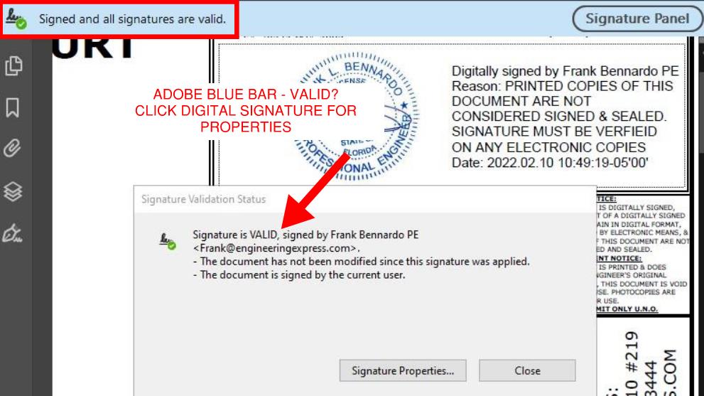
If you click the ‘Signature Properties’ button within that dialog box, you’ll see additional information about the signature such as the third party that is validating the signature (in this case it’s Entrust.
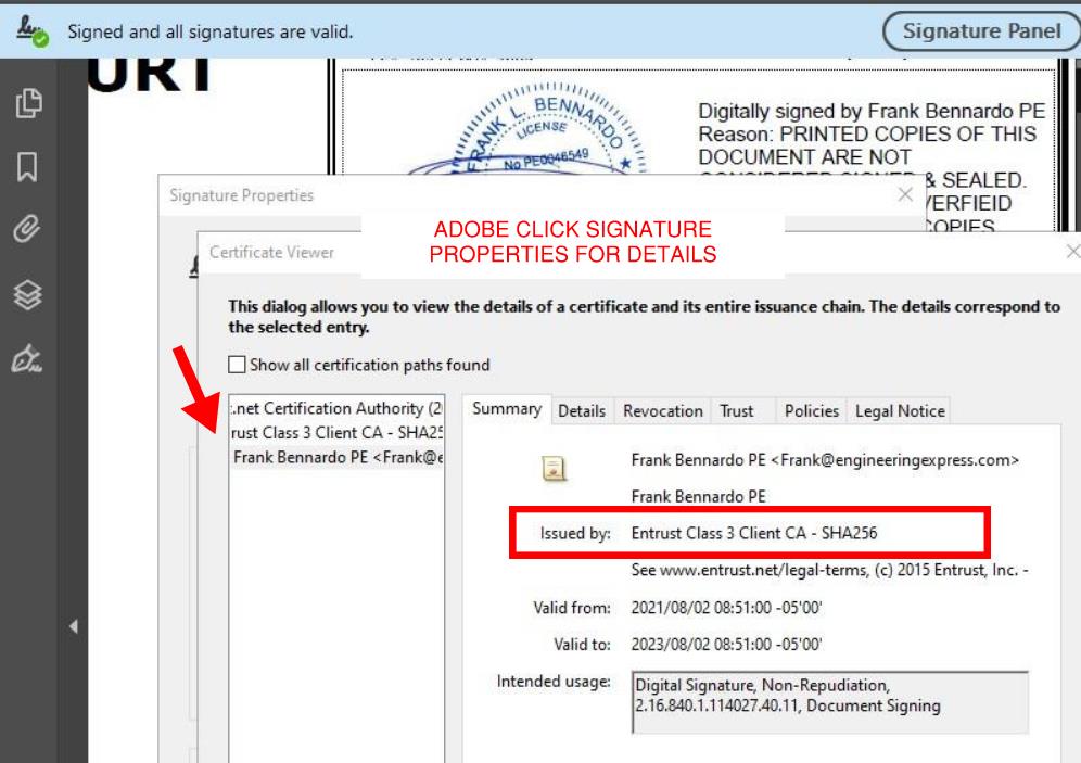
Learn more about Adobe digital signature verification from their website by clicking here.
How To Verify in Bluebeam
Verifying a digitally signed document in Bluebeam is similar but not as obvious as Adobe. No blue bar appears but there are 2 ways of verifying:
Method 1: Right Click The Digital Signature and select ‘properties’ to reveal the signature properties:

Method 2: Use the Information Panel – to show the signature panel in Bluebeam, go to Window > Panels > Signature OR press Alt+4. if the current document has been digitally signed, it will show as per the below in the signature panel:
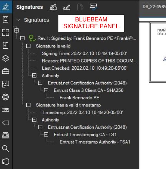
Learn more about how to verify digital signatures in Bluebeam by clicking here.
For more information about digital & electronic signatures from our Knowledge Base, click here.
Tell us how can we improve this post?
How To Use Performance Evaluations – TER’s – Calculator Reports Purchased From Engineering Express
READ BELOW BEFORE USING NON SITE-SPECIFIC PERFORMANCE EVALUATIONS
FROM ENGINEERING EXPRESS FOR YOUR PROJECT
General Information About Non Site-Specific Plans:
Certified Performance Evaluations (also referred to as Master Plans, Technical Evaluation Reports (TER’s), Generic or Non Site-Specific Plans) you receive contain a physical or digitally certified engineer seal. They are intended to be used to assist in obtaining a building permit and in constructing the component conveyed in the plan.
In all cases using a non-site specific plan, additional documentation is required to serve as approval of use of the purchased document for the intended location.
The design professional providing the site-specific approval for use then becomes the responsible party for their use at that location. This additional documentation is provided by others and not part of the purchase of generic plans or Technical Evaluation Reports (TER’s) from us.
At no time is construction to be performed without the review and approval by another party of the documents purchased regarding the applicability, limitations of use, and proper selection of plan detail options for the intended installation.
In all cases, completed work shall be inspected and approved by others before approval for use including but not limited to the municipality having jurisdiction, architect and/or engineer of record, and permitting contractor which is not our responsibility or part of this purchase.
The documents you purchase from us unless otherwise stated are for sole approval of a pre-engineered, non-site-specific building component subject to the stated limitations of use only and are NOT intended to serve as approval for the construction of any design or installation.
ALSO, AT NO TIME IS ANY PHOTOCOPY OR UNSEALED DOCUMENT TO BE USED OF PLANS FOR PERMIT UNDER ANY CIRCUMSTANCES. BUILDING CODES REQUIRE AN ORIGINAL, CERTIFIED DOCUMENT FOR EACH PERMIT TO BE VALID FOR USE.
Using Certified Performance Evaluations, TER’s & Other Reports
The Generic Plans & Technical Evaluation Reports (TER) we provide are structural performance evaluations of the subject building component and do not contain a site-specific address. The certification of those documents approves the limitations of use as stated, NOT that the building component can be used at a specific location. That is the responsibility of others as described herein.
THIS ALSO INCLUDES THE USE OF PERFORMANCE EVALUATIONS SUCH AS MIAMI DADE NOA’S, FLORIDA PRODUCT APPROVALS, TEXAS TDI EVALUATIONS, & ICC EVALUATION REPORTS WHICH FOLLOW THE SAME REGULATIONS AS OUR GENERAL PLANS & TER’S.
The design professional or user of the original, certified documents (never photocopies) shall carefully review each detail for applicability to their site-specific condition and gain approval of use for their application by others.
Engineering Express remains available for questions via email, online chat, or phone for questions or clarifications of the information within the purchased document and as contained herein which may result in additional engineering consultation fees.
Site-specific review and approval and customized & site-specific design plan services are also available which can be performed by this office or another licensed professional.
Using Certified Design Calculator Reports With Addresses Generated By Engineering Express
Printouts from online calculators may come with a site-specific address. It is understood and agreed that the address, as well as all inputted information, is provided by the purchaser at the time of purchase. By agreeing to purchase the document, you understand and affirm that we have not been contracted to a site-specific study, field investigation, or review design plans by others to provide the result you purchased.
The site-specific address you provide serves to bind the document to your permit as is required by code and does not constitute that a site-specific or field review has been performed by this firm to authorize their use.
The documents also contain information explaining this, as well as the fact that the certified results are to be reviewed by a design professional along with other required construction documents to obtain a permit for construction and use.
The information provided in the purchased document shall at all times be reviewed and approved by others for applicability and accuracy of the intended use prior to permitting and construction.
This office is solely providing a result based on the information you provide to us, that you have affirmed to us is accurate at the time of purchase, and that you have had an opportunity to consult with us prior to use if at all in doubt or have any questions about the use of the document we provided. Information regarding contacting us is provided below.
About Digitally Signed Documents
Digitally signed documents typically contain a disclaimer box limiting the use of the document to a specific contractor with a geographic zip code limitation and approved date range to apply for an electronic permit. Digitally signed documents also contain encryption to verify the authenticity of the document which shall be verified by electronic means by others before use.
Digitally signed documents must remain digital and become invalid for use once printed. Scanned copies of printed digitally sealed plans are no longer considered digital and are invalid for use.
The zip code provided in the disclaimer is provided solely to limit repeated use of the document and is not intended to serve as approval that the purchased document is valid for use within that zip code or any site-specific address contained within.
Signed documents may also contain a building floor elevation to which the use is limited to which is requested and provided solely to limit misuse of the signed document.
Certification at a specific address and building floor is the responsibility of others as described herein.
The date limitation is intended to limit the amount of time the permittee has to submit the document with the electronic application for permit. The document is valid for use within the limitations and building codes provided on the purchased document for submittal for permit during the approved date range only.
More information about digitally signed documents can be found by clicking here.
About Physical Printed ‘Hardcopies’
Documents that are physically printed (also known as hard copies) are signed and sealed with an embossed or ‘wet’ ink seal by the certifying design professional.
For these documents to be valid for use, the ORIGINAL document must be presented to the approving municipality. PHOTOCOPIES OF PRINTED DOCUMENTS ARE NOT CONSIDERED SIGNED AND SEALED AND ARE NOT VALID FOR USE.
This firm is not responsible for the use of any photocopied document of our signed and sealed work.
Additionally, markings or alterations to original signed and sealed documents invalidate our certification and require additional review prior to use.
Each signed and sealed document contains information on how to obtain an originally signed and sealed version.
More information about physically signed documents can be found by clicking here.
About Generic Documents Purchased For Building Components Attached To Structures
Documents purchased for host-attached building components (such as overhangs, wall-mounted signs, and rooftop mechanical equipment) DO NOT certify the building component for use on any specific project.
Each of these performance evaluations requires another design professional to review and approve the document for the intended site-specific application including the integrity of the host structure to withstand the additional forces placed by the building component at the time of the worst-case design condition (such as during a hurricane, snowstorm, earthquake, maximum occupancy load, etc).
THE DOCUMENTS PURCHASED THROUGH THE ONLINE PLAN STORE OR DOWNLOADED FROM A STATE EVALUATION SITE (SUCH AS MIAMI DADE NOA’S OR FL PRODUCT APROVALS) DO NOT DO THIS. ADDITIONAL STEPS MUST BE TAKEN PRIOR TO PERMITTING AND CONSTRUCTION.
The purchased documents solely state the performance limitation of the building component to the loads and design wind/snow/seismic/forces listed within the evaluation.
The actual code-minimum design forces for your site-specific project may be HIGHER than the limitations of the purchased document which shall be determined, reviewed, and approved by others and not part of our certification or your purchase.
The determination of the applicability of the use of the purchased documents is the sole responsibility of others and not purchased or included in the document you obtain from us.
Engineering Express can provide a quotation for these additional site-specific services.
Click Here to apply for access to our quoting system to submit a site-specific design request.
About Generic Documents Purchased For Freestanding Building Components
Documents purchased for freestanding building components (such as fences, freestanding pergolas, A/C and generator pads, and ground-mounted signs) contain limitations of their use and may contain equivalent design information (such as wind, snow, geotechnical, and seismic equivalent values).
These documents DO NOT approve the use of the building component for YOUR APPLICATION. The documents we provide state that IF your application meets the listed limitations of use, the building component can withstand the imposed code-minimum design forces and limitations as stated on the respective plan.
The determination of the applicability of the use of the purchased documents is the sole responsibility of others and not purchased or included in the document you obtain from us.
Engineering Express can provide a quotation for these additional site-specific services.
Click Here to apply for access to our quoting system to submit a site-specific design request.
Other:
While any licensed professional can provide the site-specific information required for use with the purchased documents as described herein, this office welcomes the opportunity to quote these additional services for other businesses.
Click Here to apply for access to our quoting system to submit a site-specific design request.
Certified documents are only valid for the state, building code, and limitations of use listed in the original, certified document. For use in states and building codes other than listed, contact the office for further evaluation which may require alterations to the performance limitations or review and certification by a licensed professional in the state requested.
Please note that while homeowners may purchase documents from our plan store, we do not perform any consultation services directly with homeowners.
If you are a homeowner and purchased certified documents from our plan store, please have your contractor contact us, or work with a local licensed professional to complete your application for permit which shall include their approval for use of your purchased documents for your specific project.
We are not responsible for any installation deficiencies that occur from the misuse of any certified document purchased from us. Any deviations from the specifications in our plans, alterations, or markings to our certified documents or use without consulting a design professional is strictly prohibited and INVALIDATE OUR CERTIFICATION.
Use of the purchased documents indemnifies & saves harmless the engineer & firm for all cost & damages including legal & appellate fees resulting from deviations of the certified plan as well as material fabrication, system erection, & construction practices beyond which is called for by local, state, & federal codes and standards of care.
The determination of the applicability of the use of the purchased documents is the sole responsibility of others and is not included in the document you obtain from us.
Engineering Express can provide a quotation for these additional site-specific services. Click Here to apply for access to our quoting system to submit a site-specific design request.
Contact this office with any questions or to request a design consultation which is required prior to permitting and construction to ensure proper use of these documents and a safe, code-compliant design.
Tell us how can we improve this post?
FAQ When will I receive my order? How long does it take to get my digitally signed-sealed file sent to me?
For Online plan orders, we do our best to get your digitally signed and sealed file reviewed, sealed by an engineer, & emailed back to you within 24 hours / the next business day.
If a plan is requested in the morning (Eastern Time), it is typically available the same business day.
Digitally sealed files are also uploaded and available to you via your Plan Store Dashboard.
For online plan order hardcopies that are mailed:
We review, seal, and send out plans that are requested in physical (hardcopy) format the same business day via UPS ground. These plans are typically delivered overnight in the South Florida area. Give the plans 24-48 hours to be received.
Custom, site-specific projects
Projects that are quoted are delivered in accordance with our signed contracts & are managed through our ExpressPass System.
Tell us how can we improve this post?
FAQ Why is there an expiration on digitally signed-sealed plans and how does that work for permitting?
Because a digitally sealed plan can be copied and reused while maintaining the digital signature certification, plans produced by engineering express that are not site-specific are encoded with limitations of use that restrict their use for permitting to a single project.
Engineering Express encodes master plans with the permitting contractor, zip code restriction, and a date at which the permit must be applied for using that plan. If any of these three items don’t fit the intended permit, the digitally signed & sealed file is not to be used to obtain a permit.
NOTES:
- If the date needs to be extended beyond the expiration for the intended permit, click here to contact the office & discuss your needs or start a chat with us.
- The zip code restriction validates a small geographic region for use while maintaining master plan sheet status and not creating a site-specific project. Site-specific projects require more engineering design & liability and are quoted separately.
Tell us how can we improve this post?
FAQ The date on my plans is old – Do I need a plan with a current date?
Plans & TER’s are dated when sealed and are tied to the listed building codes. The original sealed hardcopy versions are valid throughout the code cycle. The digitally sealed files that are not site-specific are encoded with an expiration date which would be listed in a red information box on the document. Site-specific projects that are digitally sealed are valid for use throughout the code cycle.
Remember, photocopies of originally sealed files and altered digitally sealed files are not valid to be used for permit. Only original engineering documents may be used to comply with code.
If you have any other questions, chat or contact us.
Tell us how can we improve this post?
FAQ I have a technical question on an online plan. Can you help me?
Please email us your question at [email protected] or send us a Live Chat.
Tell us how can we improve this post?
FAQ I received a hardcopy (printed) plan and need a digitally signed-sealed file. What do I do?
You will need to place a new order in our online plan store for the same plan but select ‘digitally sealed file’ under the ‘plan format’ option & re-pay for the plan.
If you can return the physical plan we will provide Tokens as credits for additional orders. See our Refund policy for more.
Tell us how can we improve this post?
FAQ What’s the difference between a hardcopy and a digitally signed – sealed file?
Hard copies are only to be used physically and digitally signed and sealed files electronically only. You can find more information here: EngineeringExpress.com/wiki/whats-the-difference-between-a-digitally-sealed-plan-and-a-scanned-digital-copy-of-a-plan
Tell us how can we improve this post?
FAQ I’m a homeowner in need of a site specific plan / custom project. Can you help?
Unfortunately Engineering Express does not work directly with homeowners for site-specific projects.
Visit EngineeringExpress.com/directory/ for a list of S. Florida engineering firms that could help you with your request or search online for an engineer near you.
Tell us how can we improve this post?
FAQ I received a comment from the city / building department / plan reviewer on an online plan. What do I do?
FIRST: Get the permit # & plan reviewer’s contact information.
THEN: Get the comments IN WRITING.
LAST: Provide us with our order # (for online orders) or Project # (for site-specific ExpressPass orders).
Forward that information to [email protected]. We are not going to be able to help you without ALL the above information.
Note: comments that request additional work that was not part of our project scope may be subject to additional fees which will be discussed with you before the additional work begins.
Tell us how can we improve this post?
FAQ I placed an order for engineering through E-Tempest / one of your online affiliates. How can I find out the status?
Please contact E-tempest directly to know the status of your order.
Tell us how can we improve this post?
FAQ I ordered a project through E-Tempest. What’s the process for receiving a digitally signed-sealed file?
Engineering Express provides engineering review & certification of orders placed through E-Tempest shutter software. If you ordered the digitally signed and sealed file from E-Tempest, it will be emailed to you as a PDF attachment. If you requested Hard copies but need a digitally signed – sealed file, please contact E-Tempest directly.
Tell us how can we improve this post?
FAQ How can I get my digitally signed – sealed file resent to me?
Use the live chat during business hours or use our Contact Form for the most reliable service.
Tell us how can we improve this post?
FAQ I need to place an online plan order for a digitally signed-sealed file. How does that work?
Visit EngineeringExpress.com/store & search for the plan you need. We recommend beginning by the brand needed.
Once you find the plan, you will be able to select the output format you need before you add the product to your cart.
After the order gets processed, the digitally sealed file will be emailed as a secure, encrypted PDF file to the email provided at the checkout.
Critical to understanding is that this file cannot be printed, which invalidates the encryption. Digitally signed and sealed files are designed to be directly uploaded to ePermit systems. Scanned copies do not contain the encryption and are not validated for use.
Tell us how can we improve this post?
FAQ What digital signing company does Engineering Express use for digitally signing design plans?
Engineering Express uses both Entrust & Identrust to digitally sign files. Both are in conformance with all known state regulations and are Adobe compliant.
Some local jurisdictions are picky though. If they require one company over another please let us know and we’ll use the appropriate digital signature encryption.
By default we use Entrust.
Tell us how can we improve this post?
Whats The Difference Between a Digitally Signed Plan, Electronic Seal, & Scanned Digital Copy of a Plan?
HISTORY
Back in the day, kings used wax to seal an envelope to prove its authenticity. That seal evolved over time to become variations of paper embossing and ink ‘wet’ sealing up until this day to certify blueprints by architects and engineers. In today’s digital world, a more secure solution is needed.
Engineering documents are required to have a proper seal in all states in the US. Here’s the rule for Florida our native state: FAC 61G15-23.001. Other states follow similar regulations.
SCANNING
The FAX machine used to be the ‘digital’ way to transmit paper from one source to another. Paper was ‘digitized’ and ‘recreated’ after transmission through phone lines. The recipient might even view the paper file on their computer screens, seeing a ‘digitized’ version of the paper original.
This concept was later refined to allow printers/copiers/scanners to ‘scan’ in the paper copy and create a digital ‘PDF’ or similar file copy.
Keep in mind that in the case of engineering and architectural plans, this is just a ‘digitized’ representation of an originally sealed file, and not a ‘digitally sealed’ set of plans.
DIGITALLY SIGNED PLANS – SO WHAT’S THE DIFFERENCE?
A file that is digitally signed (typically used for electronic permitting systems) takes any PDF set of plans, whether it was originally sealed or not, and ‘encodes’ a digitally sealed key onto the PDF. In the case of digitally sealed plans, half of the key is on the file itself and the other half is typically stored in the cloud in a secure location by a company that has already validated the person signing it. that person (a licensed engineer or architect in this scenario), has gone through an application and verification process with this approved ‘third party’ validation service and has received not only a password, but in many cases a USB Flash Drive ‘key’ to further authenticate their certification.
These plans can be verified by clicking the blue bar at the top of the real PDF or clicking the digital signature itself and viewing the signer’s information and document properties. NO BLUE BAR OR VALID SEAL? It’s not real. The digital signature needs to show as verified by an authorized third party (such as Entrust, Globalsign, or Identrust) and not via a local or unknown source.
Keep in mind each state has its own digital signature requirements which need to be verified before submitting digitally signed plans. That information can be found on each state’s respective board of engineers’ website.
Also, digitally signed documents lock and encode the ‘file’, not each page. While it is technically possible via special software to put a digital seal on every page, only a single page is required to have the seal as that’s the lock and key for the FILE, not pages. It’s a different mindset to seeing seals on each page as in the past. What is possible however is to place a seal ‘stamp’ on each page, then digitally seal the file to lock the integrity.
Remember the rule: Once digital, always digital. Once hard copy, always hard copy. Translation: Digitally sealed plans can only exist as native to digital worlds. Once a hard copy – sealed plan is scanned, that’s not the originally sealed file!
Sometimes, municipalities and reviewing authorities do rely on a paper version of a digitally sealed file and vice versa at some point in their permitting and inspection process, but to be proper the originally certified document must be submitted and use beyond that is verified by the source document (examples include as a product evaluation from ICC, FL, Miami, TDI, or a permit set on record at a building department that’s printed for field convenience).
ELECTRONICALLY SIGNED PLANS – A LESSER ALTERNATIVE
Some states (such as Florida) must offer a ‘free version’ of a digital seal method to be compliant with their laws. For this reason, an ‘Electronic Seal’ has been created. This allows self-signing of a digital file (using Adobe in itself to digitally stamp a plan that’s NOT verified by a third-party). These electronic, unverified plans need to be accompanied by an affidavit signed, sealed, and scanned by the engineer or architect that proves its authenticity. More about this can be found in FL at FAC 61G15-23.005 (other states are similar).
This frequently gets confusing for building departments who sometimes still ask for an affidavit even though a true ‘digitally sealed’ version has been presented. The below helps explain each for Florida.
Also, find below a PDF presentation Engineering Express has made for building officials and has even presented in seminars to municipalities to explain.
FLORIDA RULE
Florida Rule (our corporate home) regarding digital signatures can be found by clicking here. Rules from other states to which our engineers are personally licensed here can be researched online and adopt similar rules.
As of November 2020, the Florida Administrative Code reads for DIGITALLY SEALED PLANS:
61G15-23.004 Procedures for Digitally Signing and Sealing Electronically Transmitted Plans, Specifications, Reports or Other Documents.
(1) Engineering plans, specifications, reports or other documents which must be signed, dated and sealed in accordance with the provisions of section 471.025, F.S., and rule 61G15-23.001, F.A.C., may be signed digitally as provided herein by the professional engineer in responsible charge. As used herein, the terms “certification authority,” and “digital signature” shall have the meanings ascribed to them in sections 668.003(2) and (3), F.S.
(2) A professional engineer utilizing a digital signature to electronically sign and seal engineering plans, specifications, reports or other documents shall have their identity authenticated by a certification authority and shall assure that the digital signature is: [NOTE BY AUTHOR: DIGITAL SEALS ARE AUTHENTICATED BY A THIRD PARTY AND DON’T NEED AN AFFIDAVIT, THAT’S ONLY IF THIRD PARTY AUTHENTICATION IS NOT USED. SEE BELOW FOR 61G15-23.005 THAT PERTAINS TO ELECTRONIC VS DIGITAL SEALS]
(a) Unique to the person using it;
(b) Capable of verification;
(c) Under the sole control of the person using it; and,
(d) Linked to a document in such a manner that the digital signature and correspondingly the document is invalidated if any data in the document is changed.
(3) The affixing of a digital signature to engineering plans, specifications, reports or other documents as provided herein shall constitute the signing and sealing of such items.
(a) A digitally created seal as set forth in rule 61G15-23.002, F.A.C., may be placed where it would appear if the item were being physically signed, dated and sealed.
(b) The date that the digital signature was placed into the document must appear on the document in accordance with subsection 61G15-23.001(4), F.A.C., and where it would appear if the item were being physically signed, dated and sealed.
(c) The engineering plans, specifications, reports or other documents being digitally signed and sealed shall include text to indicate the following and place it where an original signature would appear if the item were being physically signed, dated and sealed:
1. The same information required by subsection 61G15-23.002(2), F.A.C., if a digitally created image of the seal is not use;
2. The item has been digitally signed and sealed; and,
3. Printed copies of this document are not considered signed and sealed and all signatures must be verified on any electronic copies.
[excerpt, see the FAC link above for more about the sealed format]
The ELECTRONIC METHOD requires an affidavit that validates the seal in the event there is no third party doing so (like in the digital seal).
THIS IS DIFFERENT THAN AN ELECTRONIC SIGNATURE THAT NEEDS AN AFFIDAVIT. THAT’S COVERED UNDER 61G15-23.005 AND DOES NOT APPLY TO OUR DIGITAL SEALS! PLEASE DO NOT ASK US FOR THAT FORM, DIGITAL SEALS ARE 3RD PARTY APPROVED AND EXEMPT FROM THIS REQUIREMENT PER FLORIDA STATUTES.
MORE ON THE TOPIC:
Click Here to download our PDF Presentation to building officials regarding digital vs. electronic signatures.
Also, see our page EngineeringExpress.com/Signature for verification of our principal engineer’s signature and more on this rule requirement.
Also, click here to learn how to use certified pre-engineered master plans, TER’s & Evaluation Reports provided by Engineering Express
Tell us how can we improve this post?
FAQ: What do I do if a TER or Generic Performance Evaluation isn’t approved for a permit?
Why Your TER Might Get Rejected — and How to Fix It
A Technical Evaluation Report (TER) is an engineer-certified evaluation of a product’s structural performance limits (wind, gravity, etc.). However, submitting a TER alone does not guarantee approval by a permitting authority. Various factors during the permit review process can lead to additional requirements or rejection if submitted documentation doesn’t meet the project-specific expectations.
What Is a Technical Evaluation Report
A TER is a document that describes the capacity of a building product or component based on testing or rational engineering analysis. It outlines performance limits such as allowable wind pressures or load capacities, but does not inherently address project-specific conditions like site exposure, risk category, or unique installation parameters.
Common Reasons a TER Is Not Approved for Permit
1. Lack of Project Certification
Some Authorities Having Jurisdiction (AHJs) require a Design Professional (PE/SE) to certify that the TER applies to your specific job conditions. A generic TER may demonstrate product limits but not verify suitability for the actual structural context
SOLUTION: A Design Professional needs to certify that the TER/plan meets the job conditions either by a letter, site-specific plan, or other building-department approved method.
2. Unsealed or Uncertified Submission
If the TER submitted is unsigned, uncertified, or lacks the required seals, many plan reviewers will reject the document because it doesn’t meet code documentation standards.
SOLUTION: Order sealed copies of the TER from the Online Plan Store or have your engineer provide sealed documentation
Insufficient Copies for Review
Building departments often require multiple sealed copies for record retention and cross-discipline review.
SOLUTION: Provide additional sealed copies as requested by the reviewer.
4.Need for Supplementary Engineering Documentation
Reviewers may ask for additional calculations, drawings, or clarifications related to loads, connections, or code compliance.
SOLUTION: Work with your building engineer or request additional supporting calculations from Engineering Express through a Project Request.
5.Product Use Outside TER Assumptions
TERs are based on defined test conditions and installation assumptions. If a product is used outside these limits, permitted authorities may not accept the TER.
SOLUTION: Perform a site-specific structural analysis or adapt the TER through engineering calculations tailored to the actual installation scenario.
6. Permitting Authority Is Unfamiliar With TERs
In some jurisdictions, plan reviewers may not be familiar with TERs or how to interpret them, leading to unnecessary pushback
SOLUTION: Provide explanatory resources, clarify how TERs function, and reference code language defining their use. Direct reviewers to this article.
A Technical Evaluation Report (TER) is an effective tool for demonstrating the structural capacity of pre-engineered products, but it is rarely sufficient on its own for permit approval. While a TER defines performance limits, most jurisdictions require project-specific documentation that confirms the product is suitable for the actual site conditions and code requirements.
Permit success is significantly improved when TERs are used alongside site-specific engineering, including sealed plan sheets that reference the TER and address wind, seismic, and load criteria for the project location. Early coordination with the Authority Having Jurisdiction helps clarify expectations and reduces review delays.
In some regions, particularly in high-wind or hurricane-prone areas, supplementing a TER with higher-level approvals such as Florida Product Approval or a Miami-Dade NOA can further increase acceptance and streamline the permitting process.
USEFUL ARTICLES
For guidance with your next project, explore our Plans, Calculators, Knowledge Base,
or contact us directly for site-specific support
Visit Our Plan Store
Online Design Calculators
Visit Our Knowledge Base
Site specific project request
Chat with a Designer
Chat with a Designer
Site specific project request
Visit Our Plan Store
Online Design Calculators
Tell us how can we improve this post?
About Our Site-Specific Project Process (ExpressPass) 27
Building Component Design Discovery Phase And The Following Engineering Process Explained
About Engineering Express’s Building Component Design Process
Analyzing and engineering building products is complex
— But it doesn’t have to be.
With over 30 years of experience, Engineering Express has built a proven, systemized workflow that streamlines product engineering for manufacturers and the dealers who depend on it for permitting and construction.
Let’s take a closer look at the process.
Step 1: The Introductory Phase
You will agree that it’s not possible to provide a fair quote without first understanding your system and letting you select from your available options.
Engineering Express has refined this process down to a 4 hour introductory quote.
This allows us to provide you with the absolute best success plan.
What the Introducory Phase Includes
-
Scoping Call – Discuss needs and goals -
Data Collection and Organization -
Preliminary Feasibility Study To Determine Options -
Summary Report For Client Consideration
The Summary report will be used to generate a quote for step 2. You can even ‘shop it around’ for quotes from other firms adding more value to this phase.
NOTE: This phase doesn’t include any other deliverables such as answers, details or calculations. That’s next.
After we complete this phase, we will provide you with a detailed quote
that includes all options discussed and agreed upon.
Step 2: Creating The Engineering Templates
From our findings in phase 1, we will send you a full outline of the work and the detailed price quote for each step.
Our true mission is to systemize your engineering needs by creating drawing and calculation templates from the information gathered.
This will set you up for the creation of useful tools to help you quote, prepare project designs, and expedite engineering time and reduce costs.
Step 3: Creating Performance Evaluations & Site-Specific Designs
With the templates in hand, we create the deliverables you need for quoting, design, and construction.
This is typically the goal of the project which you are in touch with us every step of the way to ensure your ideal solution.
Other Amazing Possibilities
Our Amazing Calculators
Imagine putting the engineering in your hands – No calling the engineer 100 times for the perfect answer, no delays in responses, and always the perfect solution.
Our calculators allow you, your dealers, or customers to interact with the systemized calculations publicly or privately to produce the ideal design – Then quickly send that to us for rapid engineering at VIP rates
View Our Public Calculators
Learn How It Works
Our Acclaimed Plan Store
With over 700 pre-engineered plans from dozens of manufacturers for quick certification across the US, you can be assured our full-time store support staff will expedite engineer-sealed performance evaluations to your customer, allowing their designer to use them in the permitting & construction process.
We maintain the largest building product plan store in the US with great marketing and support reach for your product.
As a bonus, we include a private-labeled engineering support channel which summarizes all your customer needs – plans, calculators, site specific designs, articles, and live support into one microsite just for you.
How To Get Started With Your Building Product Evaluation
Get started on your building product design solution today.
Complete our intake form which feeds directly into our proprietary operating system EXOps – Your one stop for project quoting, management, files, and communication.
It’s custom written over years of development to best serve you.
Tell us how can we improve this post?
How Site-Specific Project Design Fees Are Determined At Engineering Express
How We Determine Site-Specific Project Design Fees
Engineering Express sends thousands of project quotes every year.
Here’s a summary of all that goes into determining site-specific project fees.
Part 1: Hourly Fees
Part of are design services are for our time & expertise.
Engineering Express uses a ‘blended rate’ for billing time which is an average over thousands of projects for the time professional engineers, designers, and support staff spend on projects.
It’s our goal at Engineering Express to systematize site-specific projects to minimize time spent on projects. We have a whole process for this.
A relatively small amount of time spent preparing designs goes a long way in executing them expediently.
Most projects at a minimum have time billed against items such as project intake, layout, drafting, detailing, design calculations, client coordination, and draft creation & reviews.

By The Numbers
The absolute minimum a site-specific project could take, even for a direct repeat of a project from start to completion, is more than 2 hours.
The average unique small project is typically no more expedient than a starting baseline of 4 hours all elements herein including.
Part 2: Certification & Liability
Consultation is for time. PE certification is for liability and years of experience and education behind our licensure.
Factors such as job size, rising professional insurance costs with large deductibles, defense of our professional certifications, upkeep of our licenses in each state, including personal and corporate licensure, are all contributing factors in how certification is divided between projects.
As storms become more frequent, buildings age, and municipalites seek difficult third-party plan reviewers, proper certification and increased liability are driving up project costs.

By The Numbers
For building product projects, the quantity of units or linear square feet is typically considered, as well as the overall project size and cost to determine a reasonable fee to be responsible for the design.
Commercial projects are billed at a higher certification rate than residential projects due to their increased liability and submission requirements.
An absolute minimum fee is also appropriate for each project to be worth certifying.
Avoid The Quote
Get instant general designs from our plan store
Hundreds of general plans. Purchase certified copies for permit. Modify them with us for your site-specific project.

Part 3: Administration & Ongoing Support
No matter how ‘easy’ the project, every so many have building department follow up.
We also need to:
- > Maintain records per our licensure requirements,
- > Answer calls & provide online chat support
- > Intake leads and provide quotes to qualified opportunities, handle follow-up, and manage declined and canceled ones.
- > Maintain a completely custom project management system (we have a full-time, in-house, local development team)
- > Maintain our website with information like this (and a lot more, necessary to help explain work and keep costs down).
- > Send invoices & statements
- > Receive & record payments
- > Perform federal and state tax requirements.
- > And much, much more.

By The Numbers
These admin costs typically account for a 20%+ markup on projects.
Typically, these costs are factored into the time estimated for each project, easily adding 1/2 hour+ to each quote.
To accomplish a certified, national presence, a team of more than eight (8) full time staff are dedicated to administrative support.
Averages, Minimums, & The Bottom Line
In 2024, the average site-specific project design fee, subtracting the 10% extremes is just over $1,200.
We have a significant number of clients in 2025 in the $800 price range (peak of the bell curve) for smaller site-specific projects AFTER we perform discovery & setup services.
In no case have we taken a site-specific project from scratch under $400 all in. It’s just not worth our time and liability (Our Online Plan Store is the place to find lesser priced certified plans.
If you want us to review your site-specific project need, start by completing the below.
Get Started With Your Project Quote Today
ExpressPass provides an unparalleled proprietary quoting, project management, communication & file management system for custom projects with our staff of engineers.
Apply for your FREE ExpressPass Membership today & discuss your needs with one of our design experts.
ExpressPass is NOT available for homeowners, only qualifying businesses. Homeowners can access hundreds of pre-engineered plans by clicking here.
New Client? – Apply For Access
Forgot your code? Email Me My Code
https://www.youtube.com/watch?v=YNrWLhCekto
Looking to log in to your Online Plan Store account instead? Click Here
Tell us how can we improve this post?
FAQ How do I submit my completed drawings to the city?
Engineering Express only provides engineer-sealed structural drawings for your project. Submitting these drawings to the city is the responsibility of the permitting contractor.
We encourage the use of qualified permit application companies to assist if you are new to the process. These companies are independent of this firm. Information provided via the below link is to assist you in your search for permit runners, generally in the South Florida area.
Tell us how can we improve this post?
FAQ I have a change in a site specific project that’s in progress / completed. What do I do?
Please contact our project manager through your ExpressPass dashboard
Tell us how can we improve this post?
FAQ I need to create an NOA / product approval for my product. What’s the process?
See Our Guide To Obtaining The Right Product Approval For You
Summary Of The Guide
Start by reading our articles about product approvals by Clicking Here. You’ll learn when they’re really needed, what information we need, how they help, and much more.
> In short, products ‘inside the rule‘ require product approval in Florida.
> This is done by a combination of testing & rational analysis as determined by code.
> Most products such as windows, doors, and roofing require extensive testing. From there, the tests can be uploaded to the State of Florida or Evaluated by an engineer. Product Evaluations allow variations such as alternate sizes, substrates, and anchoring.
> Prior to testing, a qualified firm should be retained to establish a test protocol to maximize the use of the test results. That firm needs to be independent of the lab conducting the testing.
> With testing complete, the evaluating engineer would consult with you on the best format to display the evaluation.
> For Florida Product Approvals, prior to submitting to the state, a Validator and Quality Assurance entity needs to be retained to provide the 3rd party assurance that the evaluation is performed per code and the product meets the tested parameters over time.
> After the Florida Approval is granted, the document registration number can be used for permit in Florida if the installation matches the intent of the evaluation report. Typically a local design professional (architect or engineer) is retained to establish the design criteria of the local installation and ‘approve’ the approval for use at that location/opening. Modifications may be permitted if performed within the guidelines of the building code, referenced standards, and the limitations of the evaluation.
You can search Florida & Miami Dade Product Approvals for similar examples of your product for consideration by clicking here.
When you’re ready for Engineering Express to help & have the information gathered in the articles, visit EngineeringExpress.com/Quote to apply for access & request a quote for your product evaluation.
We will contact you shortly thereafter to discuss your needs & detail & how our national certifications can help.
USEFUL ARTICLES
For guidance with your next project, explore our Plans, Calculators, Knowledge Base,
or contact us directly for site-specific support
Visit Our Plan Store
Online Design Calculators
Visit Our Knowledge Base
Site specific project request
Chat with a Designer
Chat with a Designer
Site specific project request
Visit Our Plan Store
Online Design Calculators
Tell us how can we improve this post?
FAQ I have a different brand product than the one you specify but it’s similar. How can I get mine certified for permit?
This would require the project to be site specific.
Please visit EngineeringExpress.com/ExpressPass to apply for access to request a quote for a site-specific project.
Click ‘apply for access’, fill the form and in the description box, please give us an idea of the project you are looking for. After submitting a team leader will contact you back with the following steps.
(This process can’t be done by homeowners. We recommend finding a contractor to assist or another local engineer).
Tell us how can we improve this post?
FAQ I have a different size generator than those listed on a concrete pad master plan. How can that be added?
This would require the project to be site specific.
Please visit EngineeringExpress.com/ExpressPass to apply for access to request a quote for a site-specific project.
Click ‘apply for access’, fill the form and in the description box, please give us an idea of the project you are looking for. After submitting a team leader will contact you back with the following steps.
(This process can’t be done by homeowners. We recommend finding a contractor to assist or another local engineer).
Tell us how can we improve this post?
FAQ I need an inspection done. Can you help?
Due to our exposive national demand & specialized design expertise, Engineering Express no longer performs inspections. Visit EngineeringExpress.com/directory/ for a list of S. Florida engineering firms that could help you with your request or search online for a local engineer near you.
Tell us how can we improve this post?
FAQ I’m a homeowner in need of a site specific plan / custom project. Can you help?
Unfortunately Engineering Express does not work directly with homeowners for site-specific projects.
Visit EngineeringExpress.com/directory/ for a list of S. Florida engineering firms that could help you with your request or search online for an engineer near you.
Tell us how can we improve this post?
FAQ I received a comment from the city / building department / plan reviewer on an online plan. What do I do?
FIRST: Get the permit # & plan reviewer’s contact information.
THEN: Get the comments IN WRITING.
LAST: Provide us with our order # (for online orders) or Project # (for site-specific ExpressPass orders).
Forward that information to [email protected]. We are not going to be able to help you without ALL the above information.
Note: comments that request additional work that was not part of our project scope may be subject to additional fees which will be discussed with you before the additional work begins.
Tell us how can we improve this post?
FAQ How can I modify an existing quote request placed through ExpressPass?
Please contact our project manager through your ExpressPass dashboard
Tell us how can we improve this post?
FAQ I need a wind calculation for a roof. Can Engineering Express help with that?
As of mid-20201 Engineering Express is taking a break from roof designs to focus more on other building components. Visit EngineeringExpress.com/directory/ for a list of S. Florida engineering firms that could help you with your request.
Tell us how can we improve this post?
FAQ I can’t find an order that was supposedly emailed to me. What can I do?
Please check your email spam folder.
If you still can’t or have not received it after being notified the “Completed” status of your order please email us your order information at [email protected] & ask that it be re-emailed.
Tell us how can we improve this post?
FAQ How can I change a contact for your ExpressPass site specific project?
Access your ExpressPass account with your ExpressPass code and click edit profile.
For existing projects, you will be able to change/modify the contact for your project. For new projects, you can select the new contact at the time of ordering.
You can edit modify, & delete the contact list from the edit profile page.
Tell us how can we improve this post?
FAQ I ordered a project through E-Tempest. What’s the process for receiving a digitally signed-sealed file?
Engineering Express provides engineering review & certification of orders placed through E-Tempest shutter software. If you ordered the digitally signed and sealed file from E-Tempest, it will be emailed to you as a PDF attachment. If you requested Hard copies but need a digitally signed – sealed file, please contact E-Tempest directly.
Tell us how can we improve this post?
FAQ I’m looking for a model not shown on the chart in a Technical Evaluation Report (TER). What do I do?
Engineering Express would love to have every model unit of an A/C or generator pre-engineered. We can only engineer what we’re hired to do by the manufacturer so letting them know is always an option.
If you are a contractor & in need of our help right away, you would need to order a site-specific design so we can process 1 model for 1 address efficiently & inexpensively. Visit EngineeringExpress.com/ExpressPass, to apply for an account & request a quote for a site-specific project.
Click at apply for access, fill the form and in the description box, please give us an idea of the project you are looking for, after submitting a team leader will contact you back with the following steps.
(This process can’t be done by homeowners. We recommend hiring a contractor or calling the manufacturer. We simply cannot handle the volume of homeowner requests with the price point needed & volume of information we need to obtain).
Tell us how can we improve this post?
FAQ How can I clarify my account status with Engineering Express?
If you have reason to believe your account is not in good standing, or if a designer tells you they cannot process your work due to your account status, contact our office to help you further with your request by sending an email to [email protected] or using our general Contact Us form.
Tell us how can we improve this post?
FAQ I have a question about project statuses and what DRAFT means
To understand draft & final sealed work, see this article.
Project statuses are mostly self-explanatory throughout ExpressPass & the online ordering system. If you have questions, send us a Live Chat.
Tell us how can we improve this post?
FAQ How do I check the project status of my project with Engineering Express?
Use our convenient Status Page to check your order.
If it’s an online order, you can also find the status & track your package on your Dashboard.
For ExpressPass users, log in to ExpressPass & look under ‘orders & quotes’.
Tell us how can we improve this post?
FAQ I have questions about a project we are working on
Site-specific custom projects you have hired Engineering Express to design are managed by our acclaimed ExpressPass Project management system.
If this is a new project, you can submit your request for quote from that page.
You can communicate directly with your project manager through your ExpressPass Dashboard. This notifies key staff, & logs the question & response for future reference. Direct access phone numbers for personal service are available there as well.
Project questions through this chat or general emails are discouraged and result in delays and mishandling of the communication chain.
Tell us how can we improve this post?
What is the process for submitting site specific projects to Engineering Express?
Please visit https://engineeringexpress.com/ExpressPass to apply for access to request a quote for a site-specific project.
- Click ‘apply for access’
- Fill the form
- In the description box, give us an idea of the project you are looking for
- After submitting a team leader will contact you back with the following steps (24-48 hours)
If there are any questions use the Live Chat feature or email us using the Contact form.
Tell us how can we improve this post?
Starter List In Submitting A Ground Mounted Sign For Evaluation
Signage – Ground Mounted Client Checklist
Engineering Express evaluates ground-mounted signs for structural stability. To do this, we require a drawing detailing the structural members and connections as detailed below in order to quote and execute work.
All of the information below must be provided or addressed in this drawing – an architectural detail, sketch or rendering may not be sufficient. Without the listed information below, additional coordination, fees, and time delays will accrue or we a rejection of request to quote the work if not satisfactorily provided.
Please submit a complete drawing set with details showing the information indicated below:
- Project:
- Project name, location, & address
- Project-specific conditions & limitations (if applicable)
- Sign:
- Provide dimensioned drawing of sign and all attached components
- Detail is to be clear about any open / porous sections
- Post:
- Show quantity & spacing of post(s)
- Show material & grade of post(s)
- Show size, shape, & thickness of post(s)
- Show structural connection of post (Embed in concrete or Baseplate mounted)
- Baseplate (if applicable):
- Show size, thickness, and material
- Show any proposed welds and additional gussets
- Show anchor spacing and location
- List proposed anchors (EX will check and confirm)
- Concrete Footing:
- Show size & shape of concrete footing or height from grade and host structure material
- Sign assumed centered on footing unless noted otherwise
- Show proposed reinforcement (if applicable)
- Show surrounding slab or soil conditions
- Provide detailed structural information about any special case supporting connections
- Show size & shape of concrete footing or height from grade and host structure material
- Other & Non-structural:
- Provide supporting soil conditions (if available)
- The electrical code required & county-specific information
- Any other information to be listed such as sign color, installation instructions, etc.
- This information is to be included for reference only
- Structural certification is only for sign support & connection to base.
- Certification of sign cabinet integrity to be provided separately
Also see our useful Sign Post-Connection-Footing Calculator available by membership. Contact Us to learn more.
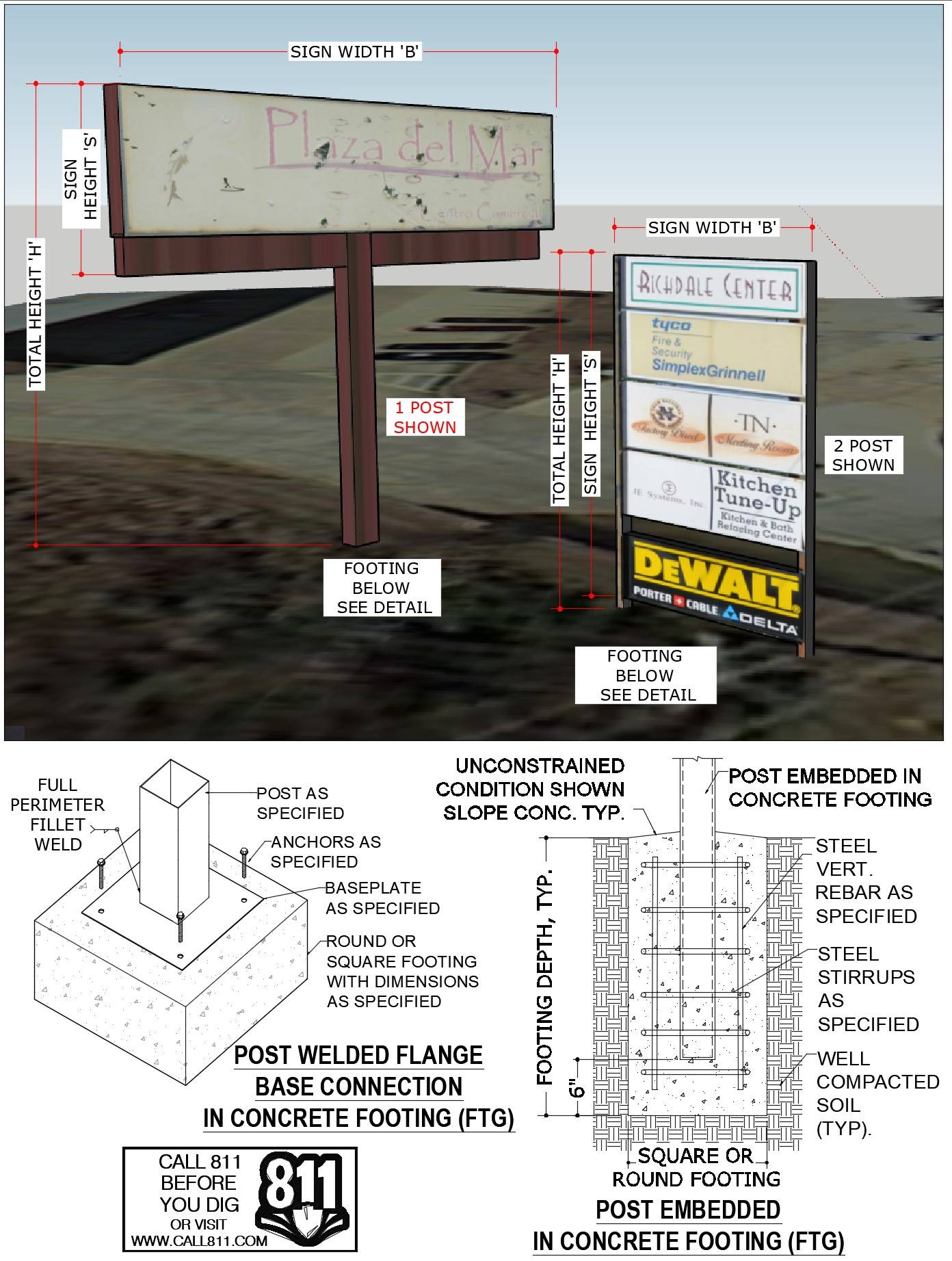
Tell us how can we improve this post?
FREQUENTLY ASKED QUESTIONS ABOUT EXPRESSPASS
FREQUENTLY ASKED QUESTIONS ABOUT EXPRESSPASS
What is ExpressPass?
ExpressPass is designed to help businesses get the certified designs you need to permit your project FAST.
It is our proprietary system that expedites your custom projects within our core departments & provides customized services for your recurring projects with transparent pricing and priority due dates.
ExpressPass is the fastest quote-to-delivery system that has ever been invented for building component design.
Click Here to watch the walkthrough video.
How do I apply for membership or log in to ExpressPass?
To apply for your FREE ExpressPass, you can do so in 3 easy steps:
ExpressPass Step 1: Once you complete your FREE application to ExpressPass and our team has approved your application, you’ll receive an email with your ExpressPass code.
Pro tip: Keep this code handy, as you’ll need it every time you want to enter your ExpressPass account.
ExpressPass Step 2: Insert your ExpressPass code in the section above.
ExpressPass Step 3: Now that you’re in your account, you can start or revise a project or view your orders and quotes.
Existing Clients:
If you are an existing client, click here to insert your code and login.
If you are having trouble logging in, click here & we will email your code.
Are fees that are generated from the order system guaranteed pricing?
While they are accurate in most cases, especially for repeat work by the same manufacturer or contractor, the fee is still largely dependent on it matching the request you submitted.
We do reserve the right to alter the order request for your approval should we feel the request doesn’t match the service and adjustments you selected.
Within ExpressPass, each service has multiple add-on adjustments to select. This allows you to add things to your quote request that you may need but is not listed in the general scope. For instance, a formal calculation booklet, expedited fees, drafting services, forensic work, etc.
Is the estimated completion date guaranteed?
It’s called ‘estimated’ for a reason. Many factors can adjust a completion date including such items as holidays not accounted for in the calculation, missing information we assumed was sent or due to us, emergencies that occur such as natural disasters where we assist in (nationally or locally), and sometimes it takes a bit longer for an engineer to review and approve the design.
The estimated completion date may also vary, depending on the terms we have set for your company. For instance, if a retainer is required, the completion date may alter if we do not receive the retainer payment upon signing. These terms are outlined in the quote.
We will do everything possible to complete on or before the estimated date but if we know we’re going to miss the date we’ll do everything possible to keep you informed- communication with our clients is something we pride ourselves on as a company.
How long does it take to receive my quote?
As soon as we receive your quote request, it is assigned to the Project Coordination Team to organize and have review.
Quotes are usually sent back for your review within 1-2 business days. However, there are some cases where we need to review multiple documents that were submitted in the request and depending on how long the review takes to come up with the best solution and pricing for you, the longest it may take longer.
What’s the difference between my ExpressPass code & my Engineering Express website login?
ExpressPass is built on our proprietary project management platform and accepts a single ExpressPass code.
Our website uses highly customized WordPress platform that follows an email-password format.
We can also store and you can access your ExpressPass access on your Engineering Express dashboard for seamless integration once logged into the Engineering Express website. If you want this connected and don’t see it there, click here to contact us to request it.
What are the core departments? And how do I request a quote if it does not fit into one of those categories?
Our core departments include:
Canopies, Pergolas & Sunrooms
Railings, Fences & Gates
Decks, Pools & Spas
Mechanical Equipment
Windows, Doors, Impact & Flood
Product Evaluations
Commercial Glazing
Signs, Poles & Solar Equipment Mounting
If your project does not fit into any of these, you can click here to send us a general email request.
Please keep in mind that general email requests will be responded to AFTER requests submitted through ExpressPass in our core departments.
Please use the ExpressPass system to expedite your needs.
Tell us how can we improve this post?
CHECKLIST FOR SCREENED ENCLOSURES, OPEN, & ENCLOSED PATIOS – SUNROOMS
CHECKLIST OF DESIGN ITEMS NEEDED FOR
SCREENED ENCLOSURES, OPEN, & ENCLOSED PATIOS, PERGOLAS & SUNROOMS
Engineering Express provides signed & sealed design plans for various types of screened enclosures, sunrooms, & open / enclosed patios attached to the main residence or freestanding.
Please review the starter list – checklist below & make sure you complete all necessary steps before submitting your sketch1.
Projects are submitted to us through our ExpressPass system for qualifying members by clicking here.
Before you order a custom patio enclosure project, be sure to check the pre-engineered Master Plans in our Online Plan Store which contain pre-certified, non-site-specific plans for permit for a variety of manufacturers and configurations.
SITE SPECIFIC PATIO ENCLOSURE JOB ORDERING CHECKLIST
Please submit a sketch1 showing all the information indicated below.
The following applies to Screened Enclosures, Sun Rooms, & Open / Enclosed Patios:
- If applicable, show roof type, dimensions (depth, skin thickness, etc.), & product approval number
- Show host building roof height & pitch
- Show overall addition dimensions (length & width)
- Show column/post spacing for all components
- Describe columns/posts & inserts if applicable, including dimensions, thickness, & material type
- If applicable, describe the host structure type (such as wood frame, CBS block, connecting to rafter tails, etc)
- Describe foundation type – size, reinforcing (or indicate if new)
- If applicable, show windows and doors, including locations, dimensions, & product approval numbers
- If applicable, describe the chair rail, including dimensions, thickness, material type, & height from ground
- If applicable, show the kick plate, including height (25% max kickplate height)
- Describe the carry beam & inserts (if applicable), including dimensions, thickness, & material type
Here’s a chart illustrating some of the many dimensions and components we need to design
an open patio / pergola / carport / louvered roof type structure.
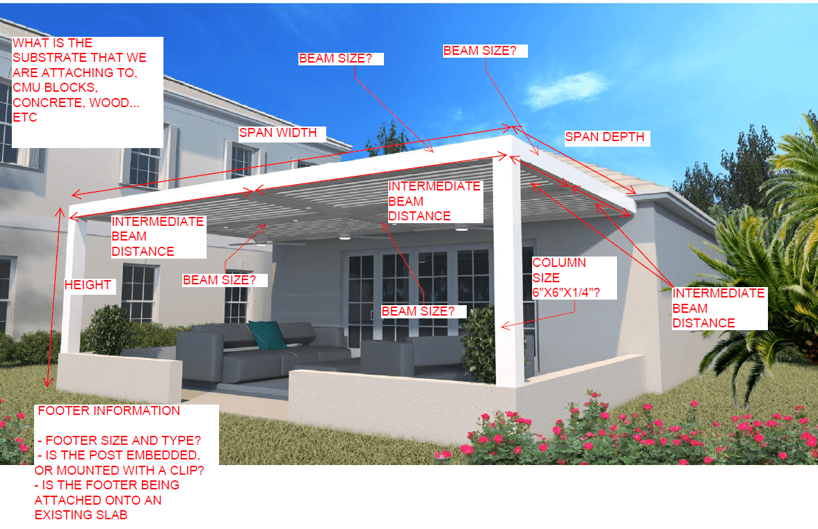
1 Click here to view-download the sample sketch shown below or click the image
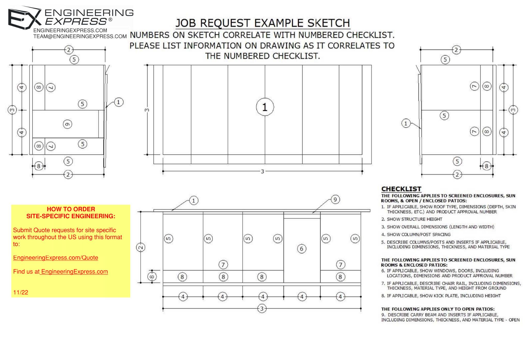
Visit EngineeringExpress.com/Quote for access to our system & to submit your project for engineering today.
Tell us how can we improve this post?
Starter List in Evaluating Your Building Component For Product Approvals & TER’s
The Ultimate Starter Checklist for Evaluating Your Building Component
Before a product can be approved, installed, or even marketed, it must prove compliance with building code performance standards.
Whether you’re developing a rooftop mechanical unit, sunroom system, or custom enclosure, success depends on one thing:
How well you prepare your submission.
CHECKLIST
Product Documentation
A complete technical package allows your engineer to understand your product immediately. Include:
-
Dimensioned drawings showing all key components, fasteners, and materials -
Assembly and section views (connection details, panel spacing, joint types) -
Weights and sizes for all models under evaluation -
Material specifications for each structural part (steel, aluminum, etc.) -
CAD / SolidWorks files for clarity (mechanical internals optional)
Performance Targets
Don’t leave your engineer guessing. Clearly outline:
-
Target design pressure or installed height -
Applicable building code version (e.g., FBC 2023, ASCE 7-16) -
Expected service conditions (indoor/outdoor, exposure) -
Whether you’ll allow reinforcement or design adjustments if needed
Don’t leave your engineer guessing. Clearly outline:
-
Target design pressure or installed height -
Applicable building code version (e.g., FBC 2023, ASCE 7-16) -
Expected service conditions (indoor/outdoor, exposure) -
Whether you’ll allow reinforcement or design adjustments if needed
Wind & Structural Loading
For wind- or structure-sensitive products:
-
Identify installation location (rooftop or ground-mounted) -
Define exposure category (C or D) -
Provide design wind speed, height above grade, and site elevation -
Note any obstructions or shielding nearby
For wind- or structure-sensitive products:
-
Identify installation location (rooftop or ground-mounted) -
Define exposure category (C or D) -
Provide design wind speed, height above grade, and site elevation -
Note any obstructions or shielding nearby
Anchorage & Connection Details
Connections are often the critical point in any design. Provide:
-
Anchor type, size, and spacing -
Substrate information (concrete, steel, aluminum, deck type) -
Frame and base-pan details with restraint locations -
Material strengths for both product and support structures
Connections are often the critical point in any design. Provide:
-
Anchor type, size, and spacing -
Substrate information (concrete, steel, aluminum, deck type) -
Frame and base-pan details with restraint locations -
Material strengths for both product and support structures
Reporting the Results
A professional evaluation should include:
-
Maximum allowable design pressures (uplift, lateral) -
Installation limitations (sizes, anchor spacing, configuration) -
Clear, permit-ready installation guidance
A professional evaluation should include:
-
Maximum allowable design pressures (uplift, lateral) -
Installation limitations (sizes, anchor spacing, configuration) -
Clear, permit-ready installation guidance
Typical Products We Evaluate
This checklist applies to a wide range of systems, such as:
-
Rooftop mechanical units and HVAC enclosures -
Sunrooms, patio covers, and screen systems -
Windows, doors, and curtainwall assemblies -
Solar racks, tanks, towers, signs, and canopies -
Custom fabricated or composite structures
If it resists wind, anchors to a building, or carries load, it qualifies.
Engineering success begins with clarity and preparation.
A well-documented submission saves time, reduces costs, and builds confidence with reviewers and clients alike.
When you partner with Engineering Express, you gain a team that understands both the code and the process — helping you move from concept to certified approval efficiently and professionally.
USEFUL ARTICLES
For guidance with your next project, explore our Plans, Calculators, Knowledge Base,
or contact us directly for site-specific support
Visit Our Plan Store
Online Design Calculators
Visit Our Knowledge Base
Site specific project request
Chat with a Designer
Chat with a Designer
Site specific project request
Visit Our Plan Store
Online Design Calculators
Tell us how can we improve this post?
Drafting Guidelines & Drawing Tool for Engineering Express Plan Submissions
Engineering Express Drafting Shop Drawings – Standards, Tips & Tricks
Use our simple tool to create a quick sketch or floor plan.
Save & submit your work to us to help with your design.
Use Our Drawing Tool
At Engineering Express, we pride ourselves on the quality of our work. Consistency is the key to a nicely presented set of engineered drawings.
This article explores several guidelines we follow when creating structural shop drawings for our clients or modifying drawings provided to us.
Title Blocks:
If you elect to use your own borders for our final work, it’s necessary that your borders conform to minimum standards. Contact Us to discuss and have us help you.
- Layers:
Take advantage of AutoCAD layers and always sort different drawing elements in their respective layers. This allows to freeze all dimensions if required or lock everything in the drawings except, for example, the detail call outs for ease of selection.
- Scale:
It is good practice to draw EVERYTHING in true scale (1:1) in Model Space and use AutoCAD’s Viewports in Paper Space to give the drawings their proper scale.
Floor plans are usually drawn at 1/8” = 1’-0”*
Glazing elevations are usually drawn at 3/8” = 1’-0”*
Details are usually drawn at 6” = 1’-0”*
*These are guidelines based on drawings done in an 11” X 17” format, scale for a 24”x 36” format will be double the one used in 11”x17”. Scales can be altered depending on the true size of the elements drawn, therefore it’s very important to draw at true scale (1 unit = 1”).
- Dimensions:
Another crucial reason to draw everything in true scale is to have consistent dimension and text sizes throughout the drawing set. Dimension Styles should be adopted based on the scale used in Paper Space (follow the factoring table below):

- Notation:
Just like in Dimensions, text styles should match the Dimension styles to have consistency in the drawings.
It is good practice to place detail callouts “aligned” horizontally and vertically on the glazing elevations, this not only more visually pleasing and easier to read but also serves a purpose when it’s time to select the detail callouts for copy/ paste operations.
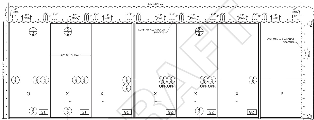
Detail callouts should have a number on top referring to the detail number and a number below the detail number referring to the page where the detail can be found (see image above).
- Blocks:
It is recommended when having repetitive elements in a drawing (eg. Title Block) to make it as a Block, it is extremely helpful and time saving when information such as revision dates need to be added to several pages in the drawing. Learn more about blocks by clicking here.
- Cover sheet:
Being the first line of information in a set of drawings, this sheet is packed with useful and vital information. It must show the Project name & address, Building Code used, General Notes, wind pressure criteria, Systems used (including product approval numbers, glass types used and system finish), scope of work and Index, in addition to detailed design information, company information, PE information and company certificate of authorization (as applicable).
Elevations:
Opening elevations should always reflect the correct dimensions based on the system used, depending on the system used, the members of a glazing system may present different profiles, it is important to draft the elevations with the correct profiles to get accurate day light opening dimensions (D.L.O). Always dimension the elevation including Rough Opening (R.O.), Frame Size (F.S.), Day Light Opening (D.L.O.).
Also display under the elevation, it’s designated Mark (shown also in the floor plan to locate the opening), manufacturer (including product approval number), quantity of openings, and Design Wind Pressures.
- Floor plans:
Floor plans are useful to show the location of the openings in the scope of work within the building. It also helps to determine Building End Zones for wind pressure calculations. The openings in the floor plan should be clearly identified with a hexagon call out and usually a letter.
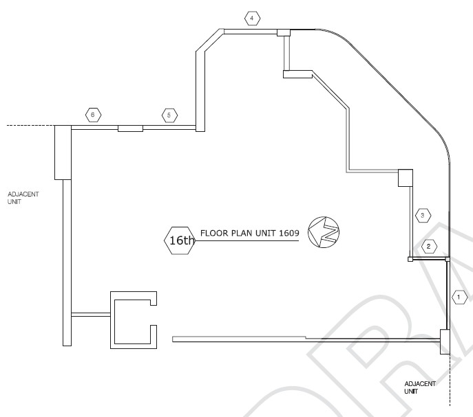
- Details:
Glazing details are usually drawn in scale 6”=1’-0” (when using an 11”x 17” format). These details must include dimensions showing R.O., F.S., D.L.O., (rough opening, frame size (after shim space), daylight opening (the part that’s completely see-through) – see image) profile size, system depth, shim space and glass bite. Also must include substrates based on architectural drawings and proper anchorage based on respective product approvals and exterior / Interior sides must be clearly identified.
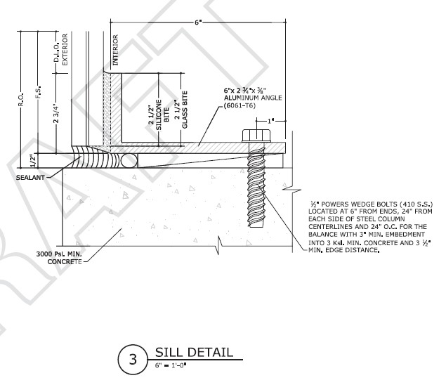
Remember, this is all PRE-ENGINEERING and subject to engineer review and approval by the firm. Engineering notes would then need to be added, calculations made, consultation with the client, and the plans must be certified by a licensed professional engineer prior to use of any kind. Contact us to discuss your drafting and engineering needs or submit a quote request through our innovative order system for the department of your need..
Tell us how can we improve this post?
Typical Information Needed For Engineering Design of a Patio-Pergola Roof
Here’s a chart illustrating some of the many dimensions and components needed to design a site specific open patio / pergola / carport / louvered roof type structure.
It’s best if you start with an existing Master Plan from one of our manufacturer partners. Mark those up & create your sketches using the information from the sample plans.
In addition to these items, we would need information such as material types, extrusion dimensions, connections, foundation, and much more. Visit EngineeringExpress.com/Quote to apply for an ExpressPass to submit your project for engineering today.
Tell us how can we improve this post?
General / Other Frequently Asked Questions 22
Understanding The Material Cost Saving of Using An Engineering Express Calculator
See this article to help illustrate the significant time and cost savings of accessing engineering through an Engineering Design-aid calculator to help quote and pre-engineer your projects prior to engaging with engineering firms.
Tell us how can we improve this post?
Understanding the 3 Types of Glazing Supports
See this article for a breakdown of the three most common types of window / door / glazing support mullions in our articles section.
Learn the difference between a mullion, supporting frame, and structural column and how they are used in a construction project.
Tell us how can we improve this post?
FAQ: Where can I find the flood zone my house or project is in?
How To Find Your Flood Zone
Understanding your property’s flood risk is essential for design, construction, insurance, and safety planning. Fortunately, identifying your flood zone is straightforward.
Step 1: Use FEMA’s Flood Map Service
Visit the FEMA Flood Map Service Portal.
By entering your address or GPS coordinates, you can quickly access the official FEMA flood map for your property.
Step 2: Review the Flood Risk Maps
The system provides detailed maps organized by city, jurisdiction, and region.
These maps give you a clear overview of the flood risks in your area.
Access them here: Flood Risk Maps
Step 3: Pinpoint Your Exact Location
Zoom in on your specific address to see your property’s flood zone designation.
This step provides the critical information required for permitting, insurance, and compliance purposes.
To illustrate, here’s a FEMA Flood Map for our corporate headquarters area, showing exactly the kind of detailed output you can expect from the site.
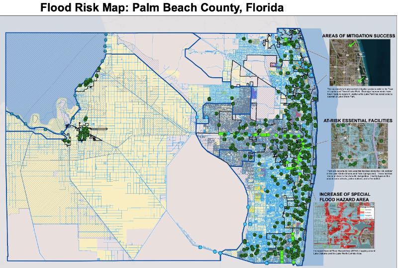
USEFUL ARTICLES
-
Additional information about flood design and protection
-
Information on changes to ASCE 24-24 flood design
For guidance with your next project, explore our Plans, Calculators, Knowledge Base,
or contact us directly for site-specific support
Visit Our Plan Store
Online Design Calculators
Visit Our Knowledge Base
Site specific project request
Chat with a Designer
Chat with a Designer
Site specific project request
Visit Our Plan Store
Online Design Calculators
Tell us how can we improve this post?
The Ultimate Guide To Creating A Window – Door Retrofit Permit Package In South Florida & Beyond
How To Apply For A Retrofit Window-Door-Garage Door Permit In South Florida & Beyond
Dade, Broward & Palm Beach Counties have adopted a unique set of rules for permitting window and door replacements (alteration level 1). Other coastal counties across the US are catching on, so the process applies when needed.
While there are variations between cities, counties, & states, these requirements are similar.
Alteration Level 1 Defined: FBC/IBC existing building Section 602.1
Level 1 alterations include the removal and replacement or the covering of existing materials, elements, equipment, or fixtures using new materials, elements, equipment, or fixtures that serve the same purpose.
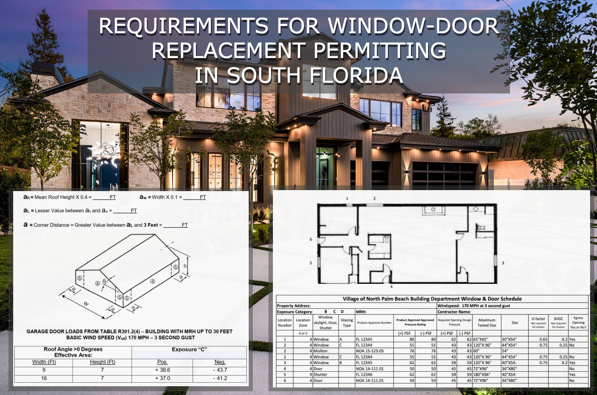
The Approval Process, Step By Step
(click on each for more information)
1) Provide Product Approvals of each unit being installed
If you don’t already have product approvals, search EngineeringPlans.com & download the product approvals you need.
You can also search Google or the Florida or Miami approval websites. EngineeringPlans also provides links to the source pages for quicker access.
The product approval is a plan that specifies the design pressure of the product for a given size, substrate, and glazing.
You’ll need to identify the size and parts you’re using and identify that limiting pressure for the permit documents.
Product Approval Markup Example
In the example below, we are using PGT PW7620A non-impact fixed window.
We’re looking for the limiting design pressure for a 72″ X 36″ window (2,3) using 3/16″ annealed glass (1)
After reviewing the approval plans, we find the limiting pressure is +-38.3psf as seen in the below markup.
We now have a design pressure for this window to compare to our site-specific condition for permit.
The municipality would likely want a markup similar to this to illustrate compliance.
(NOTE: This product example is NOT impact approved and a large missile impact system would need to cover the opening).
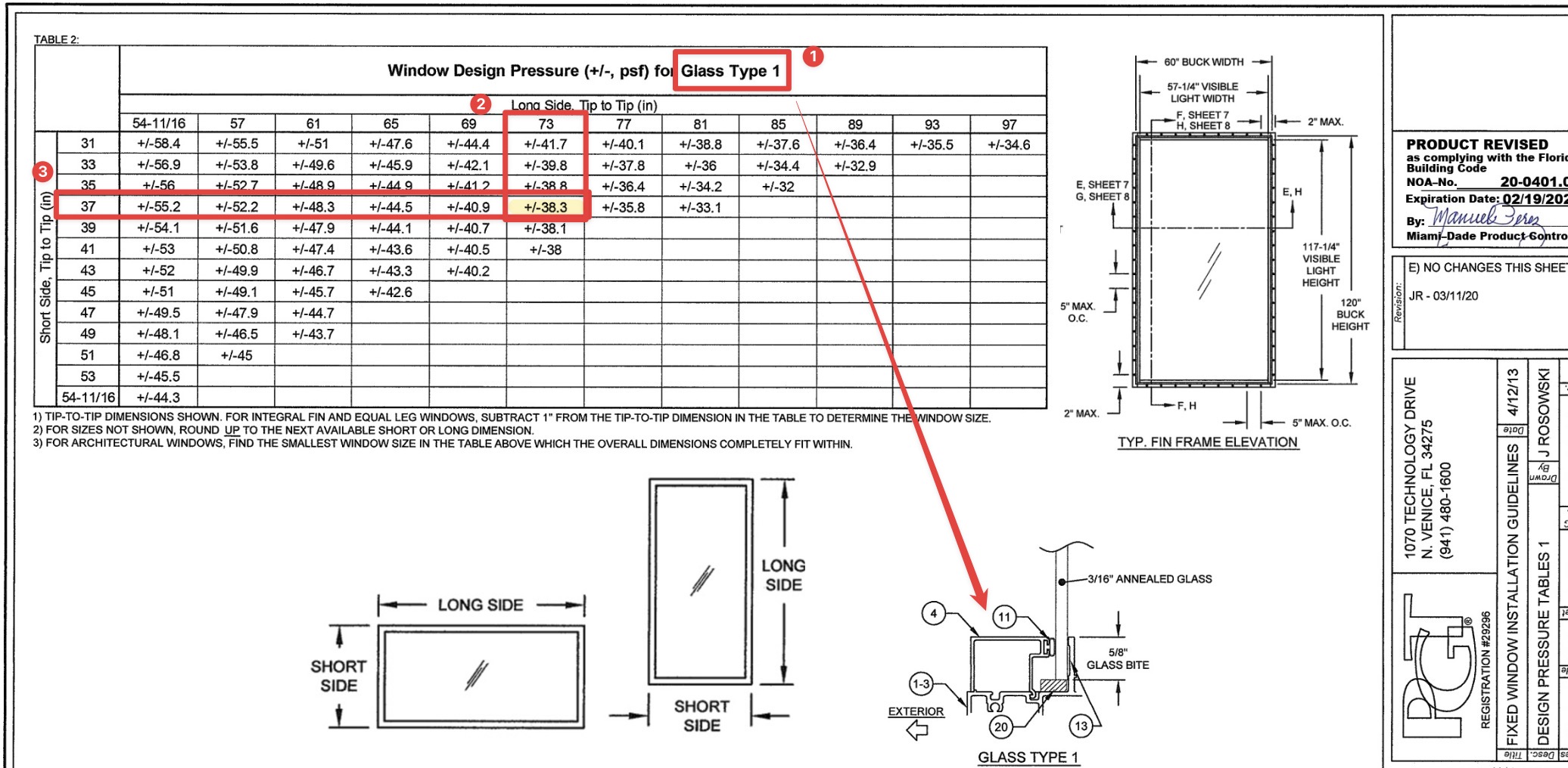
What to submit with your permit
In addition to the product approval plan set, you’ll want to submit the entire approval package.
For Miami Dade, that’s the entire NOA document that’s downloaded with the plans.
For Florida Product Approvals, find & print the cover page & submit that with the approval plans. The image to the right is the page they are looking for. (click for larger image)
Important to note, the approval documents do NOT have to be re-sealed by an engineer.
See this article that explains more.

2) Provide a signed and sealed plan from a PE or architect of all locations & pressures
A window / door retrofit plan is simply an overhead view of the structure which roughly locates each opening.
Somewhere within the plan or as an attached schedule, opening marks are called out along with sizes, pressures, and ideally the product approval being used as per above #1.
The good news is it doesn’t have to be to scale or drawn by an expert – you can do it!
Use this FREE TOOL to draw and save your sketch
Examples & Tools To Help
Click to see a small house example
Here we see a simple sketch, drawn by hand, using our simple tool, or by a CAD software program.
All that’s needed is to identify the openings being modified and their rough location in the building.
Anything close to a building corner is zone 5 (see this article which explains wall zones)
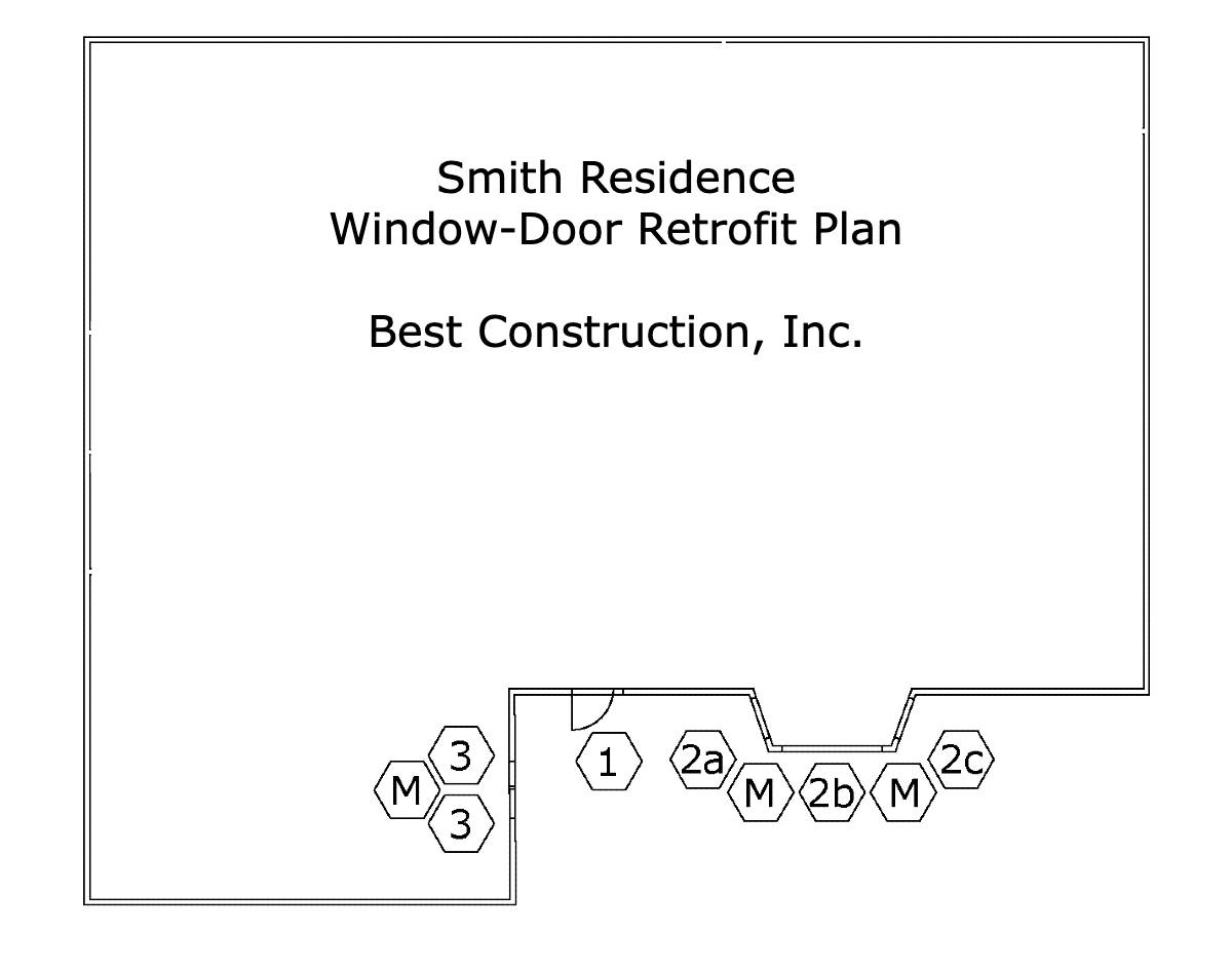
The Window & Door schedule needs to contain the following information.
Sample window/door schedule charts are found in the resources below for various municipalities.
1 – The ‘mark’ which comes from the house plan
2 – The quantity of this item
3 – The product size
4 – The ASCE 7 wind pressure zone
5 – The name/description of the product being installed
6 – The FL / Miami Dade product approval number
7 – The Design Pressures calculated for that opening (see resources below)
NOTE: The Approved Pressures must be greater or equal to the site-specific Design Pressures. This is the whole point of this exercise.
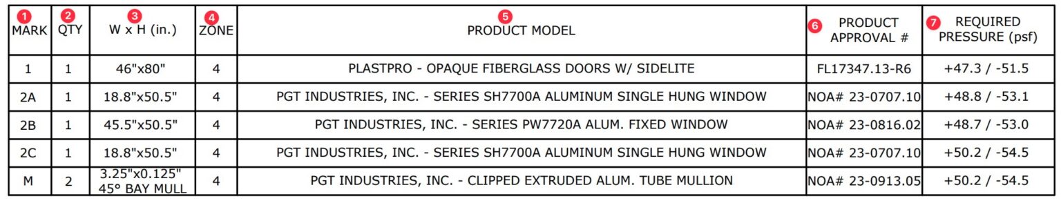
Click to see a larger condo example
Projects over 30′ height in South Florida all require a site specific plan sealed by a PE or or Architect.
While Engineering Express can assist you in creating this, it’s always quicker and less expensive if you create the drawing yourself.
You can use this tool to create the image below and submit to us.
See the small house example above for more information on the drawing requirements.
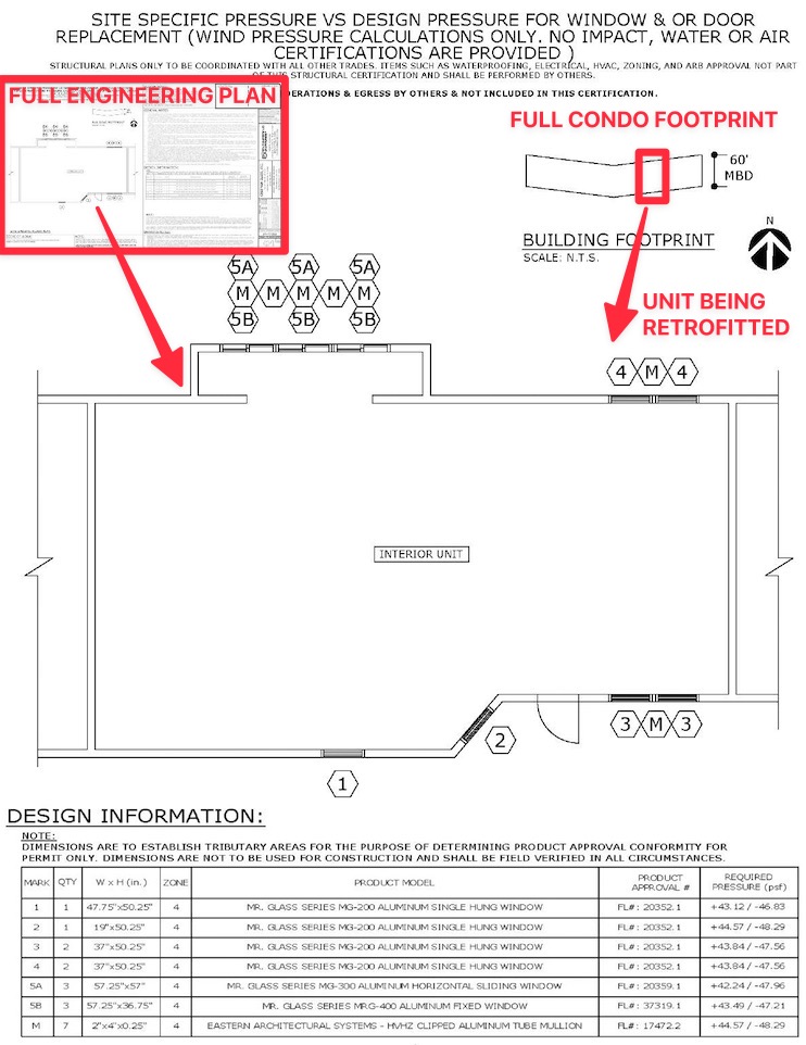
Click to see what the Village of N Palm Beach publishes as a good example
The Village of North Palm Beach publishes this example to illustrate an acceptable window-door plan and schedule.
It follows most all of South Florida requirements (see more municipality links in the resources below).
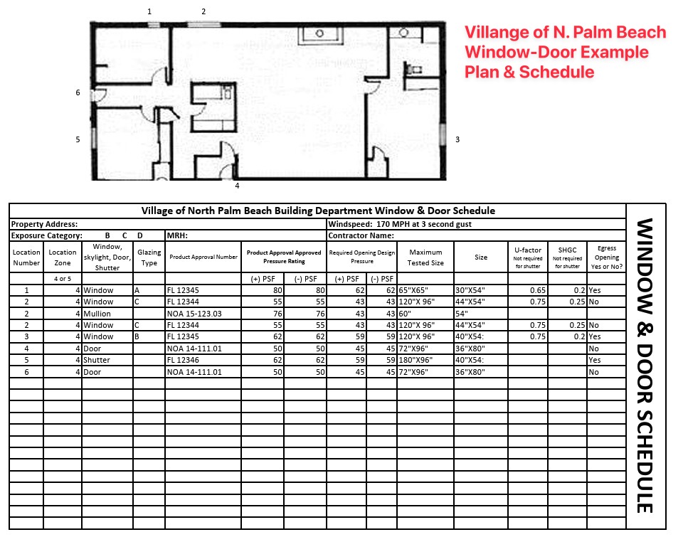
2) OR provide an unsealed plan and a ‘worst case’ design pressure chart sealed by a PE or Architect *
After creating your own sketch or using our online sketch tool, the next step is to determine your ‘worst case’ design pressures.
Engineering Express sells pre-engineered design charts for your wind speed & exposure (get those from your building department or see the notes in one of our charts).
Determine whether you’re in an interior zone 4 or more critical end zone 5. If in doubt use zone 5 (more critical).
Purchasing Certified Wind Pressures For Your Project
Engineering Express provides three resources for quickly obtaining certified wind pressures for your project.
Contact us in our online chat if you have questions.
-

ASCE7 C&C Wall Loads Calculator
$75.00 – $125.00Price range: $75.00 through $125.00
View
-
Wind Pressure Charts For Windows – Doors – Shutters
$25.00 – $30.00Price range: $25.00 through $30.00
or ( 2.5 Tokens – 3 Tokens )
View
-
Wind Pressure Charts For Garage Doors & Large Openings
$30.00
or ( 3 Tokens – 3 Tokens )
View
* Some municipalities in Broward County will accept an unsealed sketch along with the use of this ‘worst case’ wind pressure chart as it is described. Learn more here.
Engineering Express only supports clients that purchase our sealed wind pressure charts as shown above. They provide better answers and ensure an engineer is able to answer questions and assist with use as applicable.
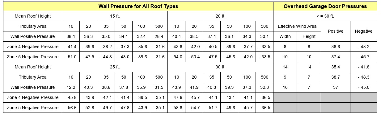
Broward County ‘worst case’ wind load chart – see municipality for applicability (2023 edition).
Click for larger image.
3) IF the structure is taller than 30′ or multifamily, a site specific plan (Option 2) is required
This plan follows the ‘larger condo example’ from option 2 above.
It does need to be sealed by a PE or Architect, but you can use this tool to help create the plan and create your own window and door schedule to bring down cost and speed up processing.
NOTE: Some municipalities use 30′ as the total roof height, while others the mean roof height. See this article for more & ask your municipality before submitting for engineering & permintting.
See these requirements visually (flowchart)
This flowchart has been adopted from the unincorporated Broward County Application Information Packet (2020)

Proceed to next steps / permitting
If you don’t already have product approvals, search EngineeringPlans.com & download the product approvals you need.
You can also search Google or the Florida or Miami approval websites. EngineeringPlans also provides links to the source pages for quicker access.
The product approval is a plan that specifies the design pressure of the product for a given size, substrate, and glazing.
You’ll need to identify the size and parts you’re using and identify that limiting pressure for the permit documents.
Product Approval Markup Example
In the example below, we are using PGT PW7620A non-impact fixed window.
We’re looking for the limiting design pressure for a 72″ X 36″ window (2,3) using 3/16″ annealed glass (1)
After reviewing the approval plans, we find the limiting pressure is +-38.3psf as seen in the below markup.
We now have a design pressure for this window to compare to our site-specific condition for permit.
The municipality would likely want a markup similar to this to illustrate compliance.
(NOTE: This product example is NOT impact approved and a large missile impact system would need to cover the opening).
What to submit with your permit
In addition to the product approval plan set, you’ll want to submit the entire approval package.
For Miami Dade, that’s the entire NOA document that’s downloaded with the plans.
For Florida Product Approvals, find & print the cover page & submit that with the approval plans. The image to the right is the page they are looking for. (click for larger image)
Important to note, the approval documents do NOT have to be re-sealed by an engineer.
See this article that explains more.
A window / door retrofit plan is simply an overhead view of the structure which roughly locates each opening.
Somewhere within the plan or as an attached schedule, opening marks are called out along with sizes, pressures, and ideally the product approval being used as per above #1.
The good news is it doesn’t have to be to scale or drawn by an expert – you can do it!
Use this FREE TOOL to draw and save your sketch
Examples & Tools To Help
Click to see a small house example
Here we see a simple sketch, drawn by hand, using our simple tool, or by a CAD software program.
All that’s needed is to identify the openings being modified and their rough location in the building.
Anything close to a building corner is zone 5 (see this article which explains wall zones)
The Window & Door schedule needs to contain the following information.
Sample window/door schedule charts are found in the resources below for various municipalities.
1 – The ‘mark’ which comes from the house plan
2 – The quantity of this item
3 – The product size
4 – The ASCE 7 wind pressure zone
5 – The name/description of the product being installed
6 – The FL / Miami Dade product approval number
7 – The Design Pressures calculated for that opening (see resources below)
NOTE: The Approved Pressures must be greater or equal to the site-specific Design Pressures. This is the whole point of this exercise.
Click to see a larger condo example
Projects over 30′ height in South Florida all require a site specific plan sealed by a PE or or Architect.
While Engineering Express can assist you in creating this, it’s always quicker and less expensive if you create the drawing yourself.
You can use this tool to create the image below and submit to us.
See the small house example above for more information on the drawing requirements.
Click to see what the Village of N Palm Beach publishes as a good example
The Village of North Palm Beach publishes this example to illustrate an acceptable window-door plan and schedule.
It follows most all of South Florida requirements (see more municipality links in the resources below).
Here we see a simple sketch, drawn by hand, using our simple tool, or by a CAD software program.
All that’s needed is to identify the openings being modified and their rough location in the building.
Anything close to a building corner is zone 5 (see this article which explains wall zones)
The Window & Door schedule needs to contain the following information.
Sample window/door schedule charts are found in the resources below for various municipalities.
1 – The ‘mark’ which comes from the house plan
2 – The quantity of this item
3 – The product size
4 – The ASCE 7 wind pressure zone
5 – The name/description of the product being installed
6 – The FL / Miami Dade product approval number
7 – The Design Pressures calculated for that opening (see resources below)
NOTE: The Approved Pressures must be greater or equal to the site-specific Design Pressures. This is the whole point of this exercise.
Projects over 30′ height in South Florida all require a site specific plan sealed by a PE or or Architect.
While Engineering Express can assist you in creating this, it’s always quicker and less expensive if you create the drawing yourself.
You can use this tool to create the image below and submit to us.
See the small house example above for more information on the drawing requirements.
The Village of North Palm Beach publishes this example to illustrate an acceptable window-door plan and schedule.
It follows most all of South Florida requirements (see more municipality links in the resources below).
After creating your own sketch or using our online sketch tool, the next step is to determine your ‘worst case’ design pressures.
Engineering Express sells pre-engineered design charts for your wind speed & exposure (get those from your building department or see the notes in one of our charts).
Determine whether you’re in an interior zone 4 or more critical end zone 5. If in doubt use zone 5 (more critical).
Purchasing Certified Wind Pressures For Your Project
Engineering Express provides three resources for quickly obtaining certified wind pressures for your project.
Contact us in our online chat if you have questions.
-
ASCE7 C&C Wall Loads Calculator
$75.00 – $125.00Price range: $75.00 through $125.00
View
-
Wind Pressure Charts For Windows – Doors – Shutters
$25.00 – $30.00Price range: $25.00 through $30.00
or ( 2.5 Tokens – 3 Tokens )
View
-
Wind Pressure Charts For Garage Doors & Large Openings
$30.00
or ( 3 Tokens – 3 Tokens )
View
* Some municipalities in Broward County will accept an unsealed sketch along with the use of this ‘worst case’ wind pressure chart as it is described. Learn more here.
Engineering Express only supports clients that purchase our sealed wind pressure charts as shown above. They provide better answers and ensure an engineer is able to answer questions and assist with use as applicable.
Broward County ‘worst case’ wind load chart – see municipality for applicability (2023 edition).
Click for larger image.
This plan follows the ‘larger condo example’ from option 2 above.
It does need to be sealed by a PE or Architect, but you can use this tool to help create the plan and create your own window and door schedule to bring down cost and speed up processing.
NOTE: Some municipalities use 30′ as the total roof height, while others the mean roof height. See this article for more & ask your municipality before submitting for engineering & permintting.
This flowchart has been adopted from the unincorporated Broward County Application Information Packet (2020)
Proceed to next steps / permitting
Next Steps & Other Considerations
So you made it through the window & door retrofit plan-schedule process… But wait, there’s more:
About Window & Door Buck Requirements
Sometimes building departments require wood buck engineering & inspection when retrofitting windows & doors.
The theory behind bucks is they need to be as strong as the anchorage of the windows being installed.
Engineering Express provides both signed & sealed 1X & 2X wood buck general plans for purchase to use in permitting. Click the links below to access them & see plan samples before purchase.
-
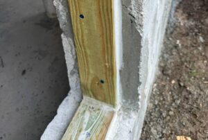
1X Wood Buck Installation Certification Plan
$160.00 – $220.00Price range: $160.00 through $220.00
or ( 16 Tokens – 22 Tokens )
View -
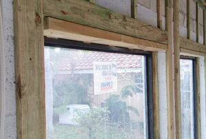
2X Wood Buck Installation Certification Plan
$160.00 – $220.00Price range: $160.00 through $220.00
or ( 16 Tokens )
View
A Word About Egress
It must be mentioned that all rooms must have a means of egress. This rule must be adhered to when retrofitting windows.
Simply put, rooms such as bedrooms need 2 means of escape in the event one is blocked.
Building departments will look at these plans to make sure there’s proper egress for all rooms.
You can read more about egress here.
Mullions & Transoms – A Closer Look
A structural mullion separates two systems in an opening.
This can be between two windows, doors with sidelites, transoms, or multiple configurations.
Mullions do not require product approval necessarily, but may manufacturers provide mullions with approvals for their windows and doors.
If an engineer designs a mullion without approval, it needs to meet the standard of the main frame, not of the windows. Typically this means a more critical deflection requirement.
Mullions need to be properly fastened to handle all wind, impact, and cyclical loading.
A design professional should be contacted if there is not product approval for a mullion meeting your design criteria.
How to determine wind loads on mullions
Per ASCE 7 commentary section 26.2, A mullion may receive wind from several cladding panels. In this case, the effective wind area is the area associated with the wind load that is transferred to the mullion.
This means you find the area of wind that acts on the mullion to determine it’s design pressure.
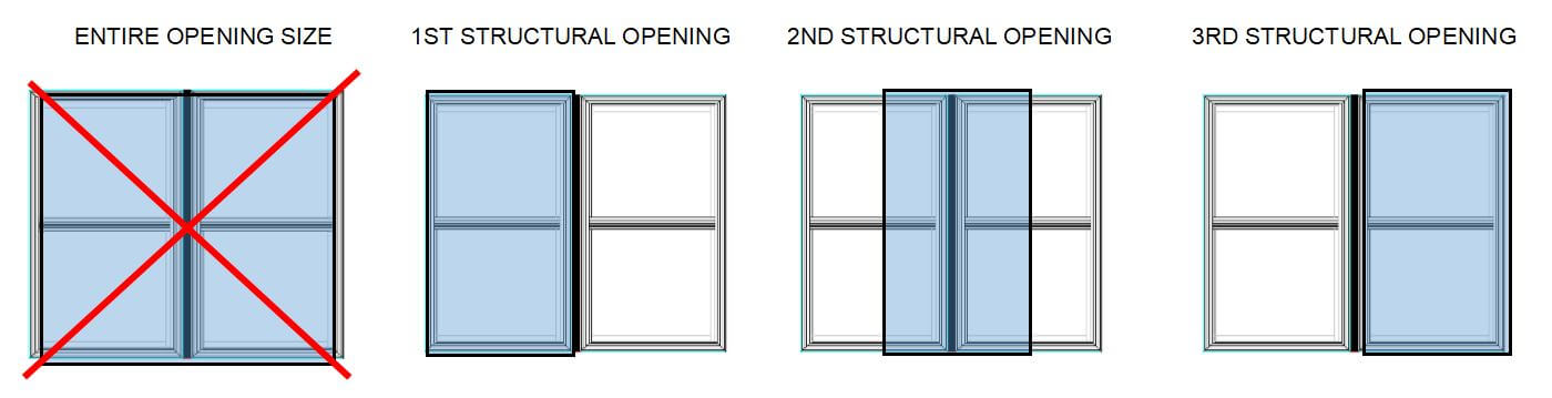
This article goes into more detail regarding mullion design.
About Garage Doors & Large Openings
The difference between a window and garage door is the size of the opening.
Large openings such as garage doors or large windows have by calculation a lower design pressure by code.
Separate engineer-sealed charts for garage door wind pressures are available for purchase to assist with permitting larger openings which can be found here
Broward County Garage Door Wind Chart
Broward County publishes Formal Interpretation #24 which provides this ‘deemed to comply’ wind chart. As you can see below, there are lower pressures for garage door sizes than smaller openings. In some situations, this chart can be referenced for permit in lieu of a sealed engineering plan chart.
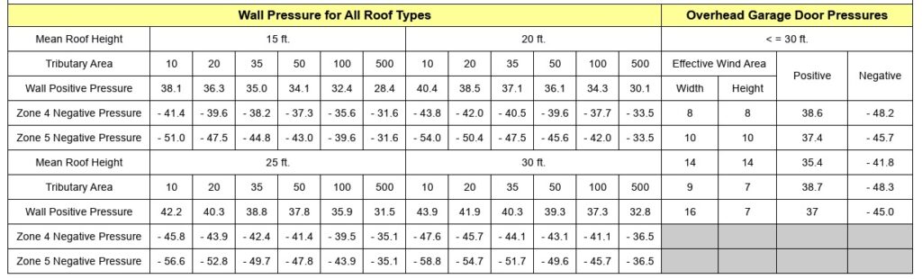
On To Permitting
Combine your product approval documents, house sketch, window & door schedule, and sealed engineering charts / calculator with your window door retrofit permit application to your municipality for processing.
Application details vary per municipality & are outside the scope of this guide.
A word about digital vs physical (paper) applications
Some municipalities in the US still use paper copies. For certified engineering documents other than product approvals, this means original, embossed or ink sealed paper – NOT PHOTOCOPIES.
Digital copies are encrypted signatures that have third-party validation to ensure they are valid. They can be shared but not modified. Many contain limitations of use such as a time frame or zip code restriction.
For more information on digital & hand sealed plans, see this article.
Sometimes building departments require wood buck engineering & inspection when retrofitting windows & doors.
The theory behind bucks is they need to be as strong as the anchorage of the windows being installed.
Engineering Express provides both signed & sealed 1X & 2X wood buck general plans for purchase to use in permitting. Click the links below to access them & see plan samples before purchase.
-
1X Wood Buck Installation Certification Plan
$160.00 – $220.00Price range: $160.00 through $220.00
or ( 16 Tokens – 22 Tokens )
View -
2X Wood Buck Installation Certification Plan
$160.00 – $220.00Price range: $160.00 through $220.00
or ( 16 Tokens )
View
It must be mentioned that all rooms must have a means of egress. This rule must be adhered to when retrofitting windows.
Simply put, rooms such as bedrooms need 2 means of escape in the event one is blocked.
Building departments will look at these plans to make sure there’s proper egress for all rooms.
You can read more about egress here.
A structural mullion separates two systems in an opening.
This can be between two windows, doors with sidelites, transoms, or multiple configurations.
Mullions do not require product approval necessarily, but may manufacturers provide mullions with approvals for their windows and doors.
If an engineer designs a mullion without approval, it needs to meet the standard of the main frame, not of the windows. Typically this means a more critical deflection requirement.
Mullions need to be properly fastened to handle all wind, impact, and cyclical loading.
A design professional should be contacted if there is not product approval for a mullion meeting your design criteria.
How to determine wind loads on mullions
Per ASCE 7 commentary section 26.2, A mullion may receive wind from several cladding panels. In this case, the effective wind area is the area associated with the wind load that is transferred to the mullion.
This means you find the area of wind that acts on the mullion to determine it’s design pressure.
This article goes into more detail regarding mullion design.
The difference between a window and garage door is the size of the opening.
Large openings such as garage doors or large windows have by calculation a lower design pressure by code.
Separate engineer-sealed charts for garage door wind pressures are available for purchase to assist with permitting larger openings which can be found here
Broward County Garage Door Wind Chart
Broward County publishes Formal Interpretation #24 which provides this ‘deemed to comply’ wind chart. As you can see below, there are lower pressures for garage door sizes than smaller openings. In some situations, this chart can be referenced for permit in lieu of a sealed engineering plan chart.
Combine your product approval documents, house sketch, window & door schedule, and sealed engineering charts / calculator with your window door retrofit permit application to your municipality for processing.
Application details vary per municipality & are outside the scope of this guide.
A word about digital vs physical (paper) applications
Some municipalities in the US still use paper copies. For certified engineering documents other than product approvals, this means original, embossed or ink sealed paper – NOT PHOTOCOPIES.
Digital copies are encrypted signatures that have third-party validation to ensure they are valid. They can be shared but not modified. Many contain limitations of use such as a time frame or zip code restriction.
For more information on digital & hand sealed plans, see this article.
Remember The Floor Plan
Many Municipalities require a plan of the building illustrating the location, type, wind pressures, & product approvals being installed.
Engineering Express has a free tool that allows you to draw these floor plans.
You can also retain the services of MySitePlan.com to draw elevations, floor plans, & site plans for you.
We can also quote any project to include these drawings for you as described in STEP 3:
Tools To Help

Free Drawing Tool
Custom Quote
Resources
Links to South Florida City-County Requirements & Resources
Here is a list of notable collected web pages municipalities in South Florida have published to document & explain this process.
Other municipalities researched were found to have similar or no resources.
Always contact the municipality you are working in to obtain the latest requirements, as they frequently change without notice!
BROWARD COUNTY
Broward County Window & Door Schedule Form (fillable)
DADE COUNTY
Miami Dade Window-Door-Shutter Help Page
Dade Window Replacement Requirements
Dade Window-Door Schedule Example
North Miami Door-Window-Shutter Checklist
Homestead Window-Door-Shutter Checklist
Miami Beach Window-Door Inspection Notice
PALM BEACH COUNTY
North Palm Beach Window-Door Form with Example
Boca Raton Window-Door Replacement Form
Useful Reources – Videos -Courses
Visit our Wind Page for an overview of wind design
Window Door Pressure Charts For Purchase (multiple options)
Garage – Large Opening Door Charts for Purchase
Use our Floor Plan Sketch Tool
1X Wood Buck Plan For Purchase
2X Wood Buck Plan For Purchase
Visit EngineeringPlans.com to easily find & download product approvals.
Take Free Glazing Courses
Learn everything from installation, ordering, accessories & more in these free courses sponsored by LearnGlazing.com.
Watch our window & door installation video
Here’s another helpful retrofit video for older homes
Final Notes About This Process
NOTE: We highly recommend consulting with a licensed professional experienced in storm wind design. Impact & cyclical pressures can only be certified by testing, and breaches during a storm can affect lives, property, and the safety of surrounding homes.
We’re here to help. reach us on our Online Chat, email [email protected], fill out our Contact Us form, call 954-354-0660, or request a quote for custom & site-specific work.
Our Opinion about ‘Worst Case’
This is just our opinion. Please consult with your designer and building official as their opinion may vary.
Many municipality webistes have used the words ‘worst case’ to identify the highest possible pressure for an opening.
In theory, the smallest opening in a building corner has the ‘worst’ pressure (zone 5, 10sqft or less). If in doubt, use this number.
But many municipality ‘worst case’ forms still show interior and exterior zones 4 & 5, various tributary area, and show various roof heights, leaving ‘some’ interpretation of their worst case to the user.
It’s our opinion if a contractor is qualified enough to estimate those items, then ‘worst case’ must mean the largest design pressure value if in doubt. BUT, if qualified to determine ‘simple’ values as described herein (or are they really qualified to begin with), then worst case is the worst case if in doubt of two options.
So if at all in doubt, use a HIGHER mean roof height, LOWER opening size, and wind ZONE 5 to find the HIGHEST design pressure.
There’s also wind speed (governed by the municipality) and ASCE 7 Exposure Category – anything near the coast is exposure D if in doubt. Otherwise, use Exposure’ C’ in Dade, Broward, and Palm Beach.
Please, ask us if you have questions – We’re here to help!
Here is a list of notable collected web pages municipalities in South Florida have published to document & explain this process.
Other municipalities researched were found to have similar or no resources.
Always contact the municipality you are working in to obtain the latest requirements, as they frequently change without notice!
BROWARD COUNTY
Broward County Window & Door Schedule Form (fillable)
DADE COUNTY
Miami Dade Window-Door-Shutter Help Page
Dade Window Replacement Requirements
Dade Window-Door Schedule Example
North Miami Door-Window-Shutter Checklist
Homestead Window-Door-Shutter Checklist
Miami Beach Window-Door Inspection Notice
PALM BEACH COUNTY
North Palm Beach Window-Door Form with Example
Boca Raton Window-Door Replacement Form
Loxahatchee Window Door Application Process with examples
Town of Palm Beach Shutter-Window-Door Retrofit Guidelines
Visit our Wind Page for an overview of wind design
Window Door Pressure Charts For Purchase (multiple options)
Garage – Large Opening Door Charts for Purchase
Use our Floor Plan Sketch Tool
1X Wood Buck Plan For Purchase
2X Wood Buck Plan For Purchase
Visit EngineeringPlans.com to easily find & download product approvals.
Take Free Glazing Courses
Learn everything from installation, ordering, accessories & more in these free courses sponsored by LearnGlazing.com.
View All Courses

https://youtu.be/k8Hw-qSlm00?si=JemGFI_wN5qH_Hvi
Watch our window & door installation video
Here’s another helpful retrofit video for older homes
NOTE: We highly recommend consulting with a licensed professional experienced in storm wind design. Impact & cyclical pressures can only be certified by testing, and breaches during a storm can affect lives, property, and the safety of surrounding homes.
We’re here to help. reach us on our Online Chat, email [email protected], fill out our Contact Us form, call 954-354-0660, or request a quote for custom & site-specific work.
Our Opinion about ‘Worst Case’
This is just our opinion. Please consult with your designer and building official as their opinion may vary.
Many municipality webistes have used the words ‘worst case’ to identify the highest possible pressure for an opening.
In theory, the smallest opening in a building corner has the ‘worst’ pressure (zone 5, 10sqft or less). If in doubt, use this number.
But many municipality ‘worst case’ forms still show interior and exterior zones 4 & 5, various tributary area, and show various roof heights, leaving ‘some’ interpretation of their worst case to the user.
It’s our opinion if a contractor is qualified enough to estimate those items, then ‘worst case’ must mean the largest design pressure value if in doubt. BUT, if qualified to determine ‘simple’ values as described herein (or are they really qualified to begin with), then worst case is the worst case if in doubt of two options.
So if at all in doubt, use a HIGHER mean roof height, LOWER opening size, and wind ZONE 5 to find the HIGHEST design pressure.
There’s also wind speed (governed by the municipality) and ASCE 7 Exposure Category – anything near the coast is exposure D if in doubt. Otherwise, use Exposure’ C’ in Dade, Broward, and Palm Beach.
Please, ask us if you have questions – We’re here to help!
LEARN MORE – BROWSE OUR WINDOW & DOOR KNOWLEDGE BASE
Browse dozens of articles on wind & wind-related design in our extensive database.
Visit our ENTIRE Knowledge Base
Tell us how can we improve this post?
What is a delegate engineer and what are their responsibilities
What is a Delegate Engineer?
A Delegate Engineer is a licensed Professional Engineer (PE) entrusted with a defined scope of work on a project. Acting as the engineer of record for that scope in particular, they are responsible for producing, signing, and sealing their own drawings and calculations.
They must also coordinate closely with the overall building Engineer of Record (EoR) to ensure their design is safe, code-compliant, and fully integrated into the overall project. Delegate engineering must be approved by the EoR for the project.
In essence, the delegate engineer is the specialist whose expertise ensures critical portions of a project are delivered with precision and accountability.

Do Delegate Engineers Differ Between States?
While there may be slight variations in specific requirements or regulations between states, a delegate engineer’s core duties and qualifications are likely to remain similar regardless of location.
These differences are usually related to licensing requirements and industry practices based on the respective state.
What is an EoR and what is their role?
The Engineer of Record is a professional engineer who is officially responsible for the design, analysis, or evaluation of a particular engineering project as a whole (such as the primary structure).
The EoR typically oversees the delegated engineering aspects of a project, ensuring that they meet applicable codes, standards, and specifications.
These include design oversight, code compliance per location, quality assurance, coordination, documentation, permitting approval, and construction support. Sometimes Architects of Record serve in this capacity.
Relationship between the EoR and the Delegate Engineer:
The EoR has no universal definition, however they have similar attributes.
An EoR is defined as “A licensed professional engineer who is in responsible charge for the preparation, signing, dating, sealing and issuing of any engineering documents for any engineering service or creative work.”
If the EoR wants something installed, such as a canopy on a building, he could hire or work with a delegate engineer, who could do the engineering solely for the desired canopy.
The delegate engineer would then create and seal the plans and calculations for the canopy.
The EoR would be responsible for ensuring that the building has the structural capacity to support the canopy.
In this case, the delegate engineer would only be liable for the canopy and its connection to the building, and the EoR would be responsible for the building’s ability to support the canopy and the integrity of the substrate the canopy is connecting to.
Why hire a Delegate Engineer?
- Shared mastery of a specific component of the structure – Hiring a delegate engineer ensures multiple experts contribute to the project.
- Higher design accuracy – More experienced minds involved means the structure is more likely to be properly designed, considering all aspects and history of similar work.
- Specialized expertise – Dispersing tasks among engineers with different niches allows for a deeper understanding of the project.
- Complementary skills – The Engineer of Record (EoR) may focus on building dynamics, while delegate engineers may specialize in specific elements like windows or canopies.
- Collaborative innovation – Combining collective experience enables engineers to design and innovate to the best of their abilities.
References & Resources
Florida Delegate Engineer Scope
Delegate Engineer vs Structural Engineer:
FBPE Newsletter
https://fbpe.org/wp-content/uploads/2015/10/october2013newsletter.pdf
Engineer of Record Article
For guidance with your next project, explore our Plans, Calculators, Knowledge Base,
or contact us directly for site-specific support
Visit Our Plan Store
Online Design Calculators
Visit Our Knowledge Base
Site specific project request
Chat with a Designer
Tell us how can we improve this post?
Whats the difference between the Miami Dade NOA Quality Assurance Date and the Building Code Expiration Date?
Learn How To Quickly Spot And Use QA Expiration & Code Dates On a Miami Dade NOA
Why This Is So Important
Miami Dade Lists an ‘Expiration Date’ on the cover page of their Miami Dade NOA’s, which is misunderstood and frequently misused.
Many times the product being used is NOT Code compliant, even though the NOA hasn’t ‘Expired’ yet.
What The Expiration Date Is And Why It’s Used
A requirement of Miami-Dade is a periodic quality assurance review of the manufacturing facility in order to obtain a Miami-Dade NOA certification.
That expiration date is the date the Quality Assurance contract expires with the manufacturer.
That date is DIFFERENT than the date of the applicable building code. Permits using the Miami Dade NOA documentation must align with the Code Expiration Date, NOT the quality assurance date.
So Why Would The QA Expiration Date Matter?
When a permit is applied for, the building code in effect is not always the code at the date of the permit application.
An open building permit in 2022 for example may have a window permit in 2024 when a new code is in effect (the 2023 FBC vs 2020 FBC).
In this case, both the code date and QA expiration date are valid and the document may be used.
If for example a 2020FBC permit was applied for on February 1, 2025, the document shown here would NOT be approved as the QA date expired.
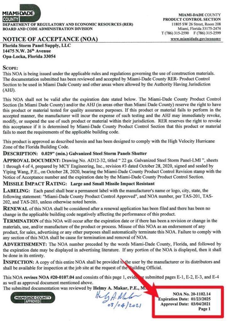
Miami Dade Cover Page Example. Click image to view this listing & source document
Where Do I Find The Building Code In The Miami Dade NOA?
Always check the general notes of the performance evaluation plans of the applicable Miami-Dade NOA to find the applicable code references.
In this case, this particular listing is approved to the 2017 and 2020 Florida Building Code but NOT the 2023 FBC.
So if a permit was pulled February 1, 2024, the QA date shows it’s current but the product would NOT BE APPROVED since it is out of current building codes.
Always check for code compliance when using any performance evaluation as the codes change. the 2023 FBC for example now uses ASCE 7-22. The prior code version used ASCE 7-16. You can also see that in the highlighted box shown.
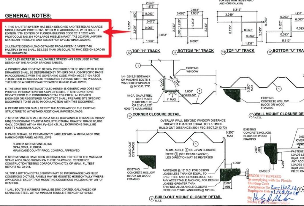
Miami Dade NOA Plan Page Example. Click image to view this listing & source document
Possible Solutions For Using An Outdated Miami-Dade NOA
Many times the applicant may be developing the updated plan or the plan may still be in review with Miami-Dade.
We suggest contacting the manufacturer to see if there is an updated plan available. It may possibly be updated as a Florida Product Approval, but not Miami Dade.
There’s also a Florida Local Product Approval Method that can allow any firm to provide a site-specific, one-time evaluation of an expired product for applicability to a specific project. Ref FS 553.8425) – read more.
Click Here to discuss that need with Engineering Express.
Quickly Search All Miami Dade NOA’s & Florida Product Approvals
Find the updated plan or another product that meets the building codes you need fast
Tell us how can we improve this post?
FAQ How do I submit my completed drawings to the city?
Engineering Express only provides engineer-sealed structural drawings for your project. Submitting these drawings to the city is the responsibility of the permitting contractor.
We encourage the use of qualified permit application companies to assist if you are new to the process. These companies are independent of this firm. Information provided via the below link is to assist you in your search for permit runners, generally in the South Florida area.
Tell us how can we improve this post?
What Services Do We Offer And Don’t Offer?
Engineering Express is a national engineering firm that only provides structural design services for building components for commercial & residential projects.
Examples of services we offer include glazing design, sunrooms, pergolas, fence and rail, mechanical equipment tie-downs and stands/curbs for wind, and product evaluations for government approval see more.
We do NOT design buildings, additions or renovations, nor do we design any non-structural work such as electrical, plumbing, or HVAC for heat or flow calculations.
Since we are a national firm specializing in design, we do not do inspections.
Who We Design For
Our model is to work closely with manufacturers to systemize their building component product to rapidly and efficiently produce site-specific building component designs across the US attached to and around residential & commercial buildings. You can see examples of some of our featured Brand Partners by clicking on our Brands Page.
If you are a manufacturer with a building component product that needs innovative national engineering design, contact us to discuss your needs or click here to learn more.
Contractors who need site-specific work from engineering we’ve designed for one of our manufacturers can either submit a quote request or find a pre-engineered plan in our Online Plan Store to use with their local design professional or us to create a site-specific application.
Who We Don’t Design For
We don’t take projects directly from contractors for one-time work in order to provide exemplary services for the manufacturers and their contractors we partner with.
We also don’t design directly for homeowners. If you are a homeowner, please work with an approved contractor for a manufacturer’s product we engineer. We don’t take any site-specific work for any type of project with a homeowner.
What homeowners can do: Homeowners are welcome to browse and purchase a pre-engineered plan from our Online Plan Store but with a warning: We do not offer refunds, modifications, or assistance in any way. Use them with your local design professional to create what you need without our involvement. Examples of when this is helpful is if you engage with one of our manufacturers which we have an online plan for and you need the sealed plan for your contractor and don’t involve us.
If you have questions
Don’t call us! We’re much more efficient using our Online Chat where we have in-house staff standing by to assist.
Thank you for your understanding and cooperation as we work to be The Fastest Engineering On The Planet for our valued clients.
Tell us how can we improve this post?
Pros and Cons of Obtaining a Florida Statewide Approval Vs A Miami Dade Approval and how a TER fits in
Which Florida Approval Is Right for You? Pros and Cons of FSA, NOA, and TER
Two common means of product evaluations in Florida are Florida Statewide Approvals (FSA’s) and Miami-Dade Notices of Acceptance (NOA’s).
To help determine whether these evaluations would be right for you, we’ve compiled a list of pros & cons for each type of evaluation.
The following reflects this firm’s interpretation based on industry experience.

![]()
Want To Learn More About Florida Statewide Approvals (FSA’s)?
See this comprehensive list of FSA Frequent Questions
Pros
of a Florida Statewide Approval (FSA)
- ✔ No Per-Sealed Copy Fees: Once an FSA is obtained, sealed product approvals can be downloaded for free from the Florida Product Approval website, with no per-project fees. This is especially beneficial for high-volume products like mechanical equipment.
While FSAs involve up-front application costs, they eliminate the need to seal individual plans for each job. If an FSA is not pursued, approvals can still be obtained on a project-specific basis, either through Local Product Approvals (for products within the rule) or Technical Evaluation Reports (TERs) for those outside the rule. Read more on this topic.
- ✔ Easy Access and Permit Efficiency: Once approved, an FSA certification is simple to access online. In many cases, it’s not even necessary to provide a printed copy to the permit office. Officials can retrieve the sealed product evaluation report themselves using the approval number. This can streamline the permit review process.
- ✔ Marketing Advantage: Having an FSA can enhance product credibility and marketing appeal. Manufacturers and distributors can state that their product holds a “Florida Statewide Approval” officially registered with the State of Florida, giving them a competitive edge, especially in high-regulation regions.
- ✔ Easier Acceptance: Although Technical Evaluation Reports (TERs) are legally valid and cannot be rejected outright if the installation falls within the scope of the signed and sealed report, they can occasionally face pushback.
FSA applications undergo peer review by a third-party validator and are subject to additional requirements, including Quality Assurance documentation. These added layers of oversight and state-level review often make FSAs more readily accepted by building officials.
While Engineering Express TERs have an excellent track record of acceptance, some jurisdictions may request additional clarification or documentation, slowing the process. In rare cases where TERs are challenged due to misunderstanding, we work directly with the reviewer to resolve any concerns.
Cons
of a Florida Statewide Approval (FSA)
-
- ✘ Higher Upfront Costs: Applying for an FSA involves multiple fees. The State of Florida charges over $500 per approval, and additional costs include Engineering Express fees for preparing and submitting the submittal package. Further expenses may include establishing a Quality Assurance (QA) contract and hiring a third-party validator, both required by the State.
- ✘ More Regulatory Requirements: FSAs require a yearly-renewed QA contract with an approved agency, adding ongoing administrative and financial obligations.
See QA and validator requirements here.
- ✘ Slow Approval Process : FSA certification takes longer to complete. Once the submittal package is prepared and submitted, there is a 2-3 month waiting period for the State of Florida to review the application and formally decide whether the submittal package is approved or rejected with comments.
- ✘ Harder to update: Updating an existing approval is also a more-involved process. Updating an approval requires a revision application to the State of Florida. If model numbers are being added to a mechanical equipment FSA for example, that requires a complete re-submission and approval, which means:
-
• Re-submitting to the State ($500+ fee per revision)
• Paying engineering fees for the updated documents
• Hiring a validator again
• Waiting 2–3 months for approval
Even after submission, the product will remain in “Applied For” or “Pending” status on the state website until officially approved.
FSAs must also be fully updated every time the Florida Building Code changes, typically every 3 years, repeating the process and its associated costs.
- ✘ Florida-Only Certification: FSAs bear a Florida professional engineer’s seal and are only valid for use within Florida. For projects in other states, local jurisdictions may require a seal from an engineer licensed in that specific state. With TER’s, Engineering Express can review codes per state and certify the report for use in over 40 states to which we are licensed and operate in.

Want To Learn More About Miami Dade NOA’s?
See this comprehensive list of Miami NOA Frequent Questions
Miami Dade Approval Knowledge Base
Pros
of a Miami-Dade NOA (Similar to FSA pros)
- ✔ No Per-Copy Fees: Once an NOA is issued, certifications can be downloaded for free from the Miami-Dade Product Control website, with no additional cost per project. This makes it ideal for high-volume products.
- ✔ Easy Access: Approved NOA documents are readily accessible online. In many cases, you don’t need to provide a printed certification to a permitting official, simply giving them the NOA number allows them to look up the sealed evaluation report directly from the county’s database.
- ✔ Marketing Value: Some manufacturers/distributors may prefer to have an NOA for marketing purposes. A common slogan seen in product advertising in South Florida is “Miami-Dade County Approved”. In addition, one of the requirements of an NOA is: “Each unit shall bear a permanent label with the manufacturer’s name or logo, city, state, model/series, and following statement: “Miami-Dade County Product Control Approved”, unless otherwise noted”. This may be seen as a desirable accolade, in comparison to competitors’ products.
- ✔ Greater Acceptance: Products with an NOA generally face fewer permitting challenges. That’s because the approval is issued directly by the Miami-Dade County Product Control Department, which is known for its rigorous review process. This includes:
- • Substantiating calculations or testing to prove product performance
• Mandatory product labeling
• Peer review by a licensed Product Control P.E.
• Annual QA audits at the discretion of Miami-Dade
• Required updates and renewal with each building code cycle
• Separate fees for QA expiration renewals
These factors add credibility and typically lead to faster, smoother acceptance by building departments.
By comparison, while TERs are valid for products outside the rule, some permit officials may not be familiar with them, which can lead to extra questions or delays. These cases are rare, and Engineering Express has a strong record of TER acceptance. We also work directly with reviewers when clarification is needed. However, if your goal is to avoid delays and ensure quick approval, an NOA is often the more straightforward option.
Cons
of a of a Miami-Dade NOA
- ✘ Higher up-front costs: Applying for a new NOA can be costly. As of 2025, Miami-Dade charges an application fee estimated at $4,300. Additional fees also apply for the certifying engineer to prepare and submit the submittal package.
- ✘ Strict Regulatory Requirements: All NOAs must comply with Miami-Dade’s product labeling rules and require an approved Quality Assurance (QA) program. Depending on the product type, further requirements may apply. For example, rooftop mechanical equipment (such as exhaust fans and ventilators) must include both engineering calculations and physical testing. See full requirements by product.
-
✘ Lengthy Approval Proces : Once the submittal package is prepared and submitted, there may be up to a 3-6 month period for Miami-Dade Product Control to review the application and formally grant approval for the NOA. In our experience, it is not uncommon for Miami-Dade to issue comments that need to be addressed prior to approval, which can lead to a longer timeframe within the aforementioned 3-6 month estimate. We suggest preparing for an 8-12 month time from start to finish.
- ✘ Complex and Costly Updates : Updating an existing NOA is also a more-involved process. Updating an NOA requires a revision application to Miami-Dade:
- • Miami-Dade charges a $1,612.50 estimated fee per revision application .
- • The certifying engineer charges fees for performing the revisions to the engineering document and submitting the application to Miami-Dade. Engineering Express’s fee may vary based on the amount of supporting calculations/documentation required, whether product requires re-testing, etc.
- • The revision application typically takes 1 to 3 months or longer to become fully approved and processed on the Miami-Dade website and additional concerns may be brought up at the time of review to comply with the latest standards of care.
- ✘ Faster Expiration: NOAs have two expiration points, each with separate renewal requirements and fees:
• Approval Expiration: typically 5 years from Miami-Dade’s issue date
• Code Cycle Expiration: when a new edition of the Florida Building Code (FBC) takes effect (every ~3 years), the existing NOA becomes obsolete unless updated
- ✘ Additional Fees: There may be additional fees that are not reflected in the above-mentioned services. For example, it is often recommend to file an application with Miami-Dade Product Control to review any test protocols to ensure Miami-Dade agrees with and approves of the proposed physical testing. Preparing said application would be covered in our NOA submittal fees, but Miami-Dade would charge an hourly rate to review and issue a verdict on said application.
- ✘ Florida-Only Certification: An NOA will bear the certifying engineer’s Florida seal. As such, the certification is formally only valid for use in Florida. For out-of-state applications, the other state may request the engineering document have a certifying engineer’s seal from their particular state. With TER’s, Engineering Express can accommodate certifying these in over 40 states in the US.
Takeaways: Our Suggestions on How to Best Utilize FSA’s, NOA’s & TER’s
A Technical Evaluation Report (TER) provided by Engineering Express is often sufficient for certifying most mechanical equipment and other products that fall ‘outside the rule’. However, as noted in the “Pros” sections above, pursuing an FSA or NOA may offer added advantages depending on your product type, permitting needs, or marketing goals.
Florida Statewide Approvals (FSA)
In our experience, when a formal product evaluation is desired, most manufacturers choose an FSA over an NOA. FSA’s typically offer similar benefits at a lower cost, with fewer regulatory hurdles.
Our recommendation: Use both a TER and an FSA to maximize flexibility and minimize delays.
• The TER is prepared first and serves as the base product evaluation document.
• It is valid for use immediately and may be submitted for permitting while the FSA is still being processed.
• Once the FSA is approved by the State of Florida, it can be used in place of the TER for certification purposes in Florida.
Miami-Dade Notices of Acceptance (NOA)
An NOA is a more involved and rigorous process compared to an FSA.
The most common reason to pursue an NOA is if your product is required to have one to be sold or installed in Miami-Dade County. This typically applies to building products such as windows, doors, and hurricane shutters.
For most mechanical equipment, however, an NOA is not required. While some building officials may ask for an NOA number, our TERs are accepted in most cases.
That said, an NOA still has its own benefits (see: “Pros of an NOA”) and can add value depending on the market and jurisdiction. If you choose to pursue one, we also recommend preparing a TER alongside the NOA.
Technical Evaluation Report (TER)
FSA and NOA documents are sealed by a Florida-licensed engineer and are therefore valid only in Florida. For projects outside of Florida, a TER can be certified in over 40 U.S. states by Engineering Express, making it the most versatile option.
TERs are available through our Online Plan Store with state-specific seals, and can also be updated quickly and cost-effectively. In many cases, updates to a TER can be reflected in the FSA or NOA at a later stage, allowing the TER to serve as a short-term solution while more formal revision applications are processed.
This approach makes full use of the speed and flexibility of the TER, while still benefiting from the added credibility and formal approval of an FSA or NOA.
Consider an Engineering Evaluation For Our Plan Store First.
We’ll create a custom version of your qualifying product plan, available for purchase in our Plan Store.
Use it for permitting and construction with site-specific approval from a design professional,even while your product approval is still processing.
Let’s set up a call to discuss.
Visit Our Plan Store
Over 700 Building Product Plans for permit & construction across the US
Click Here
USEFUL ARTICLES
-
Florida & Miami-Dade NOA Guide
-
3 Myths About Product Approval Requirements
-
How to Get a Product Approval
For guidance with your next project, explore our Plans, Calculators, Knowledge Base,
or contact us directly for site-specific support
Visit Our Plan Store
Online Design Calculators
Visit Our Knowledge Base
Site specific project request
Chat with a Designer
Chat with a Designer
Site specific project request
Visit Our Plan Store
Online Design Calculators
Tell us how can we improve this post?
Performance Requirements Typically Requested On Project Specifications
For shop drawings requested for structural permit by this office, the following are typical specifications requested. Engineering Express routinely complies with these when providing certified plans for permit:
- Delegated Design: Design , including comprehensive engineering analysis by a qualified professional engineer, using performance requirements & design criteria indicated.
- Structural Performance: shall withstand the effects of gravity loads & the following loads & stresses within limits and under conditions indicated according to SEI/ASCE 7 (latest edition).
- Seismic Loads (provided by the AOR or EOR per plans or to be calculated by the delegate engineer)
- Wind Loads (provided by the AOR or EOR per plans or to be calculated by the delegate engineer)
- Delegated Design Submittal: For to comply with performance requirements & design criteria, including analysis data signed and sealed by the qualified professional engineer responsible for their preparation.
- Design Calculations: Calculate requirements for seismic restraints
- Product Test Reports: Based on evaluation of comprehensive test performed by a qualified testing agency, for as applicable. A rational analysis may also be permitted if deemed to comply with the applicable building code.
- For glazing products within the windborne debris region:
- Provide documentation that the passes large missile impact & cyclic pressure tests per ASTM E 1886 / ASTM E 1996 according to the applicable codes & limiting requirements.
Engineering Express regularly provides this information in product evaluations and corresponding site-specific design plans for structural shop drawings for permit throughout the US.
Click here to request a quote for this work for your building component product.
Tell us how can we improve this post?
I see values for F1 and F2 on Evaluation Reports. What are they?
F1 and F2 are the limiting performance capacities of the forces in the parallel and perpendicular directions of a building component. Which one is which direction appears in a guide in each TER or corresponding test reports.
There’s also an interaction between the 2 forces that cannot be exceeded which is also explained on the reports. it’s either a linear or parabolic interaction that requires the unity of both forces to be less than 1.0. This information is to be reviewed with and by a design professional for each project.
Tell us how can we improve this post?
FAQ The building department is asking for design wind speed – risk category – exposure – address on my plan – performance evaluation – TER What do I tell them?
In the case of Performance Evaluation Plans and Technical Evaluation Reports, product evaluations, master plans, and technical evaluation reports generally list the limiting pressure forces that the product (building component) can withstand (such as these – click here).
Items such as wind speed, risk category, wind exposure are connected to the site-specific condition the building component is being installed to (per ASCE 7 & the IBC/FBC). We rate the product to a limiting force, a design professional uses these variables at a site-specific location to determine whether the building component is suitable for use in that situation.
There can be many combinations of wind speed, exposure, roof height, terrain, and other factors that determine what the design pressure is. It’s not possible for an evaluation report to list every condition and someone needs to ensure the component is good enough for the intended use.
Typically a site-specific letter by us, an architect working on a project, or another design professional is needed to connect the maximum forces on our report with the area it’s being installed. We can provide a separate quote if you cannot get someone else on the project to provide it for you. Click here to request a quote or Chat With Us.
Click here to read more about master plans and how they are used for site-specific locations.
Tell us how can we improve this post?
What are your business hours / time that you are open and what is your location?
Engineering Express is open for business from 8:30 am to 5:00 pm Eastern Time Monday through Friday. We do answer calls & chats before/after hours if we’re available.
Visiting Engineering Express is by appointment only and readily available virtually. Find our numerous offices by clicking here.
Local pickups for any plans are discontinued & are delivered via UPS next day ground. Free & VIP shipping options are available for larger orders.
Contact or chat with us if you have questions or would like to set up a visit to one of our locations.
Tell us how can we improve this post?
FAQ How can I get a copy of your W-9?
Please contact our office to assist you with a current copy or use the Live Chat.
Tell us how can we improve this post?
FAQ I need an inspection done. Can you help?
Due to our exposive national demand & specialized design expertise, Engineering Express no longer performs inspections. Visit EngineeringExpress.com/directory/ for a list of S. Florida engineering firms that could help you with your request or search online for a local engineer near you.
Tell us how can we improve this post?
FAQ I received a comment from the city / building department / plan reviewer on an online plan. What do I do?
FIRST: Get the permit # & plan reviewer’s contact information.
THEN: Get the comments IN WRITING.
LAST: Provide us with our order # (for online orders) or Project # (for site-specific ExpressPass orders).
Forward that information to [email protected]. We are not going to be able to help you without ALL the above information.
Note: comments that request additional work that was not part of our project scope may be subject to additional fees which will be discussed with you before the additional work begins.
Tell us how can we improve this post?
FAQ I need a wind calculation for a roof. Can Engineering Express help with that?
As of mid-20201 Engineering Express is taking a break from roof designs to focus more on other building components. Visit EngineeringExpress.com/directory/ for a list of S. Florida engineering firms that could help you with your request.
Tell us how can we improve this post?
Can you help me find Existing Florida Product approval, Miami Dade NOA, or ICC-ES information and plans?
If you need to find a Florida Approval, Miami Dade NOA, ICC ES, Intertek, IAPMO, or Dr. J’s Engineering number please visit EngineeringPlans.com
EngineeringPlans.com continuously synchronizes data with these agencies and indexes them for a better search and view experience.
Single-click over to the source agency site, download documents, ask and discuss, and more.
All free to use, no login required.
Tell us how can we improve this post?
FREQUENTLY ASKED QUESTIONS ABOUT EXPRESSPASS
FREQUENTLY ASKED QUESTIONS ABOUT EXPRESSPASS
What is ExpressPass?
ExpressPass is designed to help businesses get the certified designs you need to permit your project FAST.
It is our proprietary system that expedites your custom projects within our core departments & provides customized services for your recurring projects with transparent pricing and priority due dates.
ExpressPass is the fastest quote-to-delivery system that has ever been invented for building component design.
Click Here to watch the walkthrough video.
How do I apply for membership or log in to ExpressPass?
To apply for your FREE ExpressPass, you can do so in 3 easy steps:
ExpressPass Step 1: Once you complete your FREE application to ExpressPass and our team has approved your application, you’ll receive an email with your ExpressPass code.
Pro tip: Keep this code handy, as you’ll need it every time you want to enter your ExpressPass account.
ExpressPass Step 2: Insert your ExpressPass code in the section above.
ExpressPass Step 3: Now that you’re in your account, you can start or revise a project or view your orders and quotes.
Existing Clients:
If you are an existing client, click here to insert your code and login.
If you are having trouble logging in, click here & we will email your code.
Are fees that are generated from the order system guaranteed pricing?
While they are accurate in most cases, especially for repeat work by the same manufacturer or contractor, the fee is still largely dependent on it matching the request you submitted.
We do reserve the right to alter the order request for your approval should we feel the request doesn’t match the service and adjustments you selected.
Within ExpressPass, each service has multiple add-on adjustments to select. This allows you to add things to your quote request that you may need but is not listed in the general scope. For instance, a formal calculation booklet, expedited fees, drafting services, forensic work, etc.
Is the estimated completion date guaranteed?
It’s called ‘estimated’ for a reason. Many factors can adjust a completion date including such items as holidays not accounted for in the calculation, missing information we assumed was sent or due to us, emergencies that occur such as natural disasters where we assist in (nationally or locally), and sometimes it takes a bit longer for an engineer to review and approve the design.
The estimated completion date may also vary, depending on the terms we have set for your company. For instance, if a retainer is required, the completion date may alter if we do not receive the retainer payment upon signing. These terms are outlined in the quote.
We will do everything possible to complete on or before the estimated date but if we know we’re going to miss the date we’ll do everything possible to keep you informed- communication with our clients is something we pride ourselves on as a company.
How long does it take to receive my quote?
As soon as we receive your quote request, it is assigned to the Project Coordination Team to organize and have review.
Quotes are usually sent back for your review within 1-2 business days. However, there are some cases where we need to review multiple documents that were submitted in the request and depending on how long the review takes to come up with the best solution and pricing for you, the longest it may take longer.
What’s the difference between my ExpressPass code & my Engineering Express website login?
ExpressPass is built on our proprietary project management platform and accepts a single ExpressPass code.
Our website uses highly customized WordPress platform that follows an email-password format.
We can also store and you can access your ExpressPass access on your Engineering Express dashboard for seamless integration once logged into the Engineering Express website. If you want this connected and don’t see it there, click here to contact us to request it.
What are the core departments? And how do I request a quote if it does not fit into one of those categories?
Our core departments include:
Canopies, Pergolas & Sunrooms
Railings, Fences & Gates
Decks, Pools & Spas
Mechanical Equipment
Windows, Doors, Impact & Flood
Product Evaluations
Commercial Glazing
Signs, Poles & Solar Equipment Mounting
If your project does not fit into any of these, you can click here to send us a general email request.
Please keep in mind that general email requests will be responded to AFTER requests submitted through ExpressPass in our core departments.
Please use the ExpressPass system to expedite your needs.
Tell us how can we improve this post?
Glossary of Engineering Terms
Glossary of Building Component Engineering Terms & Abbreviations
These terms are published by Engineering Express to coincide with help menus for our online tools & published articles and as they relate to the Building Component Design industry.
See also our FLOOD ENGINEERING GLOSSARY for more terms related to flood engineering.
See Also SUNROOM TERMINOLOGY for a list of Sunroom terms compliments of the National Sunroom Association
Looking for our list of abbreviations?
Contact Us for any questions, clarifications, or suggestions you have regarding these items.
Glossary
| LABEL | DEFINITION |
| ADDITION ROOF TYPE | For sunroom enclosures, roof types can be monoslope for studio, shed, or other single slope style roofs or gable, also known as A-Frame. Roof type & slope affects the conversion from wind speed to pressure Learn More. |
| ATTACHED TO HOST | For our column calculators, Yes assumes pinned at top & bottom so k=1.0 and simply supported for lateral bending moment on post itself No assumes fixed at base and pinned at top (such as for freestanding aluminum structures, k=2.0 for buckling & cantilever moment for lateral on post itself) |
| AHJ | AHJ – Authority Having Jurisdiction. The entity with the authority to determine / enforce building code requirements. Typically the building department you submit permits to. |
| ASCE | American Society of Civil Engineers. A professional body that provides much of the structural engineering provisions present in the Florida and International Building Codes. Visit asce.org for more. |
| ASD (PRESSURES) | Allowable Stress Design – where the capacity of the member in question is reduced (factored down) to an allowable factored limit as opposed to ultimate pressures where the load is factored up and compared to actual capacities. |
| BEAM ALLOWABLE SPAN | Clear Beam Span of the panel or member in question between two supports. |
| BENDING STRESS | The total bending stress from a transverse force in the extreme fibers of the member in question. |
| BUILDING ENVELOPE | Simply defined, it’s the separation between the interior & exterior of a building/habitable space or air-conditioned vs. non-air-conditioned space. The ‘shell’ of a building. The building envelope is subject to ‘internal pressurization’, affecting building components that comprise the building shell. |
| CLASSIFICATION | Screened for removable acrylic sliders, open if 3 or more sides are open, solid for glass or panels. |
| CLEAR SPAN | The clear distance between supports of a member in question. |
| CLEARANCE HEIGHT | Used in our mechanical rooftop equipment calculator, typically defined by this firm as the support structure clear height, or height from grade/roof level to the bottom of the unit in question. Seek confirmation from the associated unit diagram before using this definition. |
| CODE YEAR | Select ASCE 7-16 in our online calculators only for the 2020 Florida Building Code or 2018 International Building Code (IBC). ASCE 7-10 corresponds to ASCE 7-10 and codes before IBC 2018. |
| COLUMN ALLOWABLE HEIGHT | The allowable clear span of a post from the slab to beam or knee brace above. If the resulting allowable height in a result is less than the allowable ceiling height, the result shall include knee walls or other supporting structures. |
| COLUMN SPACING | For the determination of column loads, the column spacing is the average on-center spacing between columns, in decimals for our online tools (0.5= 6”). For the determination of carry beams between columns, spacing is the clear span between two columns. Typically column spacing is the on-center spacing of columns unless otherwise defined. |
| COMPRESSIVE STRESS | The stress from a longitudinal force acting in compression on a member axially, typically for a column. |
| COMBINED STRESS UTILIZATION | See Utilization |
| COMPONENTS & CLADDING | The pieces and parts of a building or other structure that comprise the building envelope. Typical component & cladding items include windows, doors, door handles & hinges, exterior fascades, etc. ASCE-7 has specific requirements for the design of building components & components of other structures. |
| CRITICALLY WELDED | When aluminum is heated during welding, the alloys realign and weaken the member, typically within 2 inches of any heated surface. For our calculators, if a beam or column is welded at any critical point within 2 inches of the maximum moment, select ‘yes’ which loads an alternately calculated allowable stress for the aluminum selected. Click here for more on the topic. |
| DEAD LOAD (D) | Dead load is the actual self-weight of an unloaded roof, floor, or similar surface. Typically the load of sunroom roof panels, or roof trusses + underlayment + shingles or tiles, or for decks the weight of wood + connectors. |
| DEFLECTION | The bending limit of a member – see chapter 16 of the building code, typically L/180 for glass, L/60 for screen, L/240 for plaster. Click here for more. Deflection is typically expressed as L/# where L = the Clear Span of the member in question. For example, a member with a 10’ long clear span that has an allowable deflection limit of L/60 would be allowed to deflect 10/60= 0.1667’ or 2”. |
| EFFECTIVE WIND AREA | Effective wind area is the area of the building surface used to determine (GCp). This area does not necessarily correspond to the area of the building surface contributing to the force being considered. There’s an H*H/3 rule & structural break understanding to better understand. Click here to read more. |
| ELEVATION ABOVE SEA LEVEL (ELEVATION FACTOR, Ke) | A variable used in wind load calculations that allows for reductions in the calculated wind load as site elevation above sea level increases. For Every 1,000 ft above sea level, atmospheric pressure and corresponding wind pressure is decreased per ASCE 7-16 (not per ASCE 7-10). In our online tools, select 0ft above sea level if unsure or at sea level (returns 1.0 factor). |
| EXPOSURE CATEGORY | The ASCE Exposure Category reflects the characteristics of ground surface irregularities at a site in which the building or structure is to be constructed. The rougher the surface, the lower the multiplier that converts wind velocity to pressure. Learn More |
| ENCLOSURE TYPE | The type of installation being installed – typically open or enclosed (screened). Click here for more. |
| FBC | Florida Building Code. The set of rules and regulations that constructed buildings and other structures must abide by in the State of Florida. To view the FBC, click here: https://codes.iccsafe.org/codes/florida |
| FENESTRATION | Openings within a building envelope or surface such as for windows, doors, etc. These openings require design considerations typically referred to as components & cladding design in ASCE-7. |
| HIGH-VELOCITY HURRICANE ZONE (HVHZ) | A special wind region in Florida consisting of only Broward & Miami-Dade counties. The Florida Building Code may specify different conditions and requirements for the HVHZ than for what applies to the rest of Florida depending on the structure/application. For more information click here. |
| HEIGHT | The total unsupported height of a member in question. |
| IBC | International Building Code. Provides most of the wind requirements for U.S. states other than Florida. |
| IMPACT SHUTTER ANALYSIS | If yes is selected in our online tools, the calculation for area of opening switches from Width * Height to Height * Height/3. It operates on the assumption that impact shutters are tested infinite width. This operates on the assumption that mother nature cannot focus a maximum burst on too narrow or too wide of an area of wall or roof cladding. Click here for more on the topic of Effective Wind Area. |
| LATERAL LOAD ALONG POST | For column calculations, this represents a horizontal force acting on a column in question. It could come from a membrane attached to a column of some sort or entered without an axial force for columns to analyze a column member acting as a beam. |
| LIVE LOAD (L) | Total live load (roof and floor) such as snow or other code required loading. |
| LRFD (Load Resistance Factor Design) | Rather than factoring down critical loads as per the ASD (allowable stress design) method, this design method requires adding the factor to the load to compare it to the actual limiting value of a component. a 200lb force would become 400lb on a ladder that actually breaks at 400lb rather than saying a ladder that actually breaks at 400lb is reduced to 200lb to compare to the limiting load. See our Factored Load Calculator design aid and this article for more. |
| MARK | This is your label to help identify the answer on the accompanying layout drawings. It has no effect on the result other than to help you coordinate your permit documents. |
| MEAN ROOF HEIGHT, MRH | This is the average roof height from the peak to the eave. Click here to learn more. |
| MEMBER TYPE | Member corresponds to a beam for areas such as the eave edge beam above openings or columns which are the supporting mullion posts. |
| MIN OVERALL BLDG DIMENSION | Along with the mean roof height, this dimension helps set the end zone width to determine the length of end zone 5 (greater pressure area). Click here to learn more. This is the shortest building dimension. The End zone 5 is 10% of this value, 40% of the mean roof height, but not less than 3’ Click here to learn more about wall zones. |
| U.N.O. | Unless Noted Otherwise. Indicates that exception(s) may exist to a specification/code requirement under certain circumstances. |
| OVERHANG | In an enclosure or building. The overhang is the portion of the roof beyond the outer supporting wall. It’s typically limited when roof panel spans are provided in our online calculators to limit the uplift on panels & connections as well as stresses on roof panels & beam spans. |
| PE | Professional Engineer. Only licensed professional engineers & registered architects are able to provide signed and sealed engineering documents needed for a building permit. |
| PERGOLA | A structure usually consisting of parallel colonnades supporting an open roof of girders and cross rafters. |
| POSITIVE/NEGATIVE | In terms of our ASCE 7 loading conventions typically used on our online calculators or master plans, positive is the force inward into the building, negative is pushing out. Expect larger negative values due to building internal pressurization. |
| REACTION | The force at each end of the member in consideration. Typically used to verify anchorage shear, which would be perpendicular to the member in the direction of the load. |
| RISK CATEGORY | A classification of buildings and other structures by “importance levels” ranging from Categories I through IV. Used in determining wind speed (Vult). Category I has the lowest wind speeds, Categories III-IV have the highest. For more information, click here. Find wind speeds for various risk categories on the ASCE Hazard Tool. |
| ROOF TERMS | Here’s a glossary of roof terms compliments of roofs.com click to visit. |
| ROOF SLOPE | The angle of the roof relative to horizontal. It’s typically measured in angles or rise over run. In some ASCE component & cladding calculations, if the roof slope is less than 10 degrees, there is a slight reduction in pressure. If complex roof or unsure, set to >= 10 degrees on our online calculators. |
| ROOF LIVE LOAD (Lr) | The live load on a roof is the weight of any temporary objects on the roof, such as people, and equipment. The Florida and IBC codes both require a 20psf minimum roof live load in addition to the dead load & other loads that the roof must bear. Use our Factored Load Calculator to determine the total ASD or LRFD load for your project. |
| ROOF SPAN | The unsupported clear roof span length between supports. |
| SNOW LOAD | This can either be ground, roof, or drift snow, 3 very different concepts. Be sure to use the proper value for your project. |
| SUPPORT TYPE | Four our beam calculators, ‘Simple’ follows a simply supported beam (pinned-roller) M=WL^2/8, ‘Cantilever’ assumes fixed at one end and free at the other M=WL^2/2 |
| TOPOGRAPHY FACTOR Kzt | Another multiplier when converting wind speed to wind pressure. Use 1.0 for flat terrain. For areas on or near hills, this will need to be calculated elsewhere. Worst case is 3.0. Consult a design professional or contact us if not flat terrain for proper application of this coefficient. |
| TOTAL LOAD | The sum of all imposing loads on a roof or wall surface measured in pounds per square foot. These loads are factored in accordance with (Chap 16) of the Florida or International Building Code or 2018 International Building Code. Consult a design professional to be sure & see our Factored Load design calculator. |
| TRIBUTARY WIDTH | This value sets a width (ft) that’s multiplied by the uniform load (psf) to develop a load per foot (plf) on the member in question. For considerations where you already have the load per foot on a member, select 1 foot for this option. This value is typically half the distance to the left + half the distance to the right of the next supporting member. |
| ULTIMATE (PRESSURES) | The factored total force acting on a member. This is where the load value is factored up rather than reducing the ultimate stress of a member in question. |
| UNBRACED LENGTH | The factored total force acting on a member. This is where the load value is factored up rather than reducing the ultimate stress of a member in question. |
| UNIT DEPTH | Used in our mechanical rooftop equipment calculator, Typically defined by this firm as the smaller horizontal dimension (the shorter of unit width and depth). More simply, the unit’s short side. Seek confirmation from the associated unit diagram before using this definition. |
| UNIT WIDTH | Used in our mechanical rooftop equipment calculator, Typically defined by this firm as the larger horizontal dimension (the longer of unit width and depth). More simply, the unit’s long side. Seek confirmation from the associated unit diagram before using this definition. |
| UTILIZATION | Beam utilization is the sum of squares for bending & shear ((fv/Fv)^2+ (fb/Fb)^2)^0.5. For columns is the maximum of (3) equations: sum of squares of equation above and H.1-1 (fa/Fa + fb/Fb) or H.3-2 fa/Fa + (fb/Fb)^2 + (fb/Fv)^2 of the 2015 Aluminum Design Manual |
| WIND DIRECTIONALITY FACTOR Kd | For our components & cladding calculators, This is generally 0.85. Change to 1.0 only if required by the building department or special use case directed by the architect/engineer. This factor is used in the formula that converts wind speed to wind pressure & involves a reduction due to the reduced likelihood that multiple loads will occur simultaneously on a surface. Click here to learn more. |
| WIND VELOCITY, Vult (Also Wind Speed) | The peak 3-second gust wind speed. Consult your building department or engineer for governing codes. Learn more by Clicking Here Use the ATC Wind Council Site to obtain your minimum wind speed for the risk category being designed by clicking here. |
| WIND LOAD | The total force due to wind on an object. The force can be suction or positive pressure when dealing with wall & roof pressures, or total force on a freestanding object. Typically for Engineering Express the wind load is represented in PSF (Pounds Per Square Foot) & either ASD or LRFD (allowable stress or load resistance factor design). |
| WIND ZONE | ASCE wind pressure location zone – Use Zone 4 for interior (non-corner) openings. Zone 5 are any corners that result in a higher wind speed to wind pressure conversion factor. IF UNSURE, USE 5! Click here to learn more. |
List of Abbreviations Used By Engineering Express
| ABBREVIATION | MEANING |
|---|---|
| alum | aluminum |
| ASTM | American Society for Testing and Materials |
| CS | carbon steel |
| EA | each |
| edge | edge distance |
| E.D. | edge distance |
| EDDS | extra deep drawing steel |
| elev | elevation |
| embed | embedment |
| e.g. | exempli gratia or “for example” |
| EQ | equivalent |
| equiv. | equivalent |
| FSA | Florida Statewide Product Approval |
| FEA | Finite Element Analysis |
| FL # | Florida Statewide Product Approval Number |
| FLCA | Florida Certificate of Authorization |
| FS | Florida Statutes |
| ft | feet |
| Fu | ultimate tensile strength or ultimate tensile stress |
| Fy | yield strength or yield stress |
| G | specific gravity |
| GA | gauge |
| galv. | galvanized |
| GFB | grout-filled block |
| GR | grade |
| Gr. | grade |
| HVAC | heating, ventilation, and air conditioning |
| i.e. | id est or “in other words” |
| in | inch |
| ksi | 1,000 pounds per square inch (1,000 lb / in2) |
| L | length |
| lb | pound (force) |
| m | meter |
| max. | maximum |
| MD | Miami-Dade or Miami-Dade Product Control Section |
| min. | minimum |
| mm | millimeter |
| MPa | megapascal |
| N | Newton |
| NOA | Notice of Acceptance |
| NTS | not to scale |
| O.C. | on center |
| OD | outer diameter |
| Pa | Pascal (1 N/m2) |
| pcf | pounds (force) per cubic foot (lb/ft3) |
| perp | perpendicular |
| psf | pounds (force) per square foot (lb/ft2) |
| psi | pounds (force) per square inch (lb/in2) |
| EPS | expanded polystyrene |
| qty | quantity |
| ref | reference |
| SAE | Society of Automotive Engineering |
| sched | schedule |
| SDS | self-drilling screws |
| SMS | sheet metal screws |
| specs | specifications |
| SS | stainless steel |
| TAS | Testing Application Standard |
| TDI | Texas Department of Insurance |
| TER | Technical Evaluation Report |
| typ. | typical |
| ult | ultimate loads |
| UTS | ultimate tensile strength or ultimate tensile stress |
| WLL | working load limit |
| w/ | with |
| w/o | without |
| YS | yield strength or yield stress |
| # | number |
| & | and |
| Ø | diameter |
| ‘ | feet |
| ” | inches |
Contact Us for any questions, clarifications, or suggestions you have regarding these items.
Tell us how can we improve this post?
Wind Speed vs. Wind Pressure Explained
Many don’t understand how wind works & state that a product is rated to a specific wind speed. This is false advertising & not true.
There’s no such thing as “Rated to XXX MPH wind”
This is frequently seen in marketing materials which is a false & misleading statement
that comes with many unwritten disclaimers.
The Why
The formula that converts wind velocity to wind pressure has many variables. Each variable affects the resulting pressure for a given wind velocity. A 100mph wind velocity for example can produce pressures as low as in the mid-teens (psf) to upwards of 50psf, even 60psf, and more*. These variables include such features as building height, location of the area on the building, the terrain around the building, whether the building is on or near a hill, slope of the roof, size of the area in consideration, and more.
There are even two types of wind speeds and pressures that complicate things further, Allowable stress design and Load Factored Design (click here to learn more) as well as different wind codes that govern (Some use ASCE 7-05, most use ASCE 7-10, and there’s now ASCE 7-16 with yet different conversion factors for some building surfaces for the same wind velocity). Engineers deal with a common denominator when designing structures (wind pressure) which sets a uniform standard anywhere (yes even on the moon) for a force that a product can resist.
How We can help
1) Engineering Express provides certified wind charts for permit for windows, doors, and garage doors. Click Here to browse our plan store
2) Engineering Express also provides a free online tool to convert wind velocity to wind pressure. Click Here to access it
* ASCE 7-16 Exposure D, 300 ft MRH, Zones 5 and 3 respectively, 10sqft tributary area, enclosed structure, flat terrain, Kd=0.85, Forces upwards of 70psf + possible for hilly terrain, partially enclosed, Kd=1.0, at sea level.
Tell us how can we improve this post?
FAQ: What do I do if a TER or Generic Performance Evaluation isn’t approved for a permit?
Why Your TER Might Get Rejected — and How to Fix It
A Technical Evaluation Report (TER) is an engineer-certified evaluation of a product’s structural performance limits (wind, gravity, etc.). However, submitting a TER alone does not guarantee approval by a permitting authority. Various factors during the permit review process can lead to additional requirements or rejection if submitted documentation doesn’t meet the project-specific expectations.
What Is a Technical Evaluation Report
A TER is a document that describes the capacity of a building product or component based on testing or rational engineering analysis. It outlines performance limits such as allowable wind pressures or load capacities, but does not inherently address project-specific conditions like site exposure, risk category, or unique installation parameters.
Common Reasons a TER Is Not Approved for Permit
1. Lack of Project Certification
Some Authorities Having Jurisdiction (AHJs) require a Design Professional (PE/SE) to certify that the TER applies to your specific job conditions. A generic TER may demonstrate product limits but not verify suitability for the actual structural context
SOLUTION: A Design Professional needs to certify that the TER/plan meets the job conditions either by a letter, site-specific plan, or other building-department approved method.
2. Unsealed or Uncertified Submission
If the TER submitted is unsigned, uncertified, or lacks the required seals, many plan reviewers will reject the document because it doesn’t meet code documentation standards.
SOLUTION: Order sealed copies of the TER from the Online Plan Store or have your engineer provide sealed documentation
Insufficient Copies for Review
Building departments often require multiple sealed copies for record retention and cross-discipline review.
SOLUTION: Provide additional sealed copies as requested by the reviewer.
4.Need for Supplementary Engineering Documentation
Reviewers may ask for additional calculations, drawings, or clarifications related to loads, connections, or code compliance.
SOLUTION: Work with your building engineer or request additional supporting calculations from Engineering Express through a Project Request.
5.Product Use Outside TER Assumptions
TERs are based on defined test conditions and installation assumptions. If a product is used outside these limits, permitted authorities may not accept the TER.
SOLUTION: Perform a site-specific structural analysis or adapt the TER through engineering calculations tailored to the actual installation scenario.
6. Permitting Authority Is Unfamiliar With TERs
In some jurisdictions, plan reviewers may not be familiar with TERs or how to interpret them, leading to unnecessary pushback
SOLUTION: Provide explanatory resources, clarify how TERs function, and reference code language defining their use. Direct reviewers to this article.
A Technical Evaluation Report (TER) is an effective tool for demonstrating the structural capacity of pre-engineered products, but it is rarely sufficient on its own for permit approval. While a TER defines performance limits, most jurisdictions require project-specific documentation that confirms the product is suitable for the actual site conditions and code requirements.
Permit success is significantly improved when TERs are used alongside site-specific engineering, including sealed plan sheets that reference the TER and address wind, seismic, and load criteria for the project location. Early coordination with the Authority Having Jurisdiction helps clarify expectations and reduces review delays.
In some regions, particularly in high-wind or hurricane-prone areas, supplementing a TER with higher-level approvals such as Florida Product Approval or a Miami-Dade NOA can further increase acceptance and streamline the permitting process.
USEFUL ARTICLES
For guidance with your next project, explore our Plans, Calculators, Knowledge Base,
or contact us directly for site-specific support
Visit Our Plan Store
Online Design Calculators
Visit Our Knowledge Base
Site specific project request
Chat with a Designer
Chat with a Designer
Site specific project request
Visit Our Plan Store
Online Design Calculators
Tell us how can we improve this post?
Engineering 63
Protected: Calculating Site Specific Wall Wind Pressures For Windows, Doors, & Garage Doors
Design of Padel and Outdoor Sports Courts in the United States
Design of Padel and Outdoor Sports Courts in the United States
Padel courts and outdoor sports facilities, while relatively simple in appearance, are governed in the United States by a comprehensive set of structural, safety, and regulatory requirements. Their design involves not only classical civil and structural engineering considerations, but also strict compliance with building codes such as the International Building Code and loading standards like ASCE 7. In high-risk regions such as Florida, wind loading and glass resistance become critical design drivers. This document outlines the key regulatory constraints and engineering obligations that must be addressed to ensure safe, compliant, and constructible padel and outdoor sports court projects.

Zoning, Permitting, and Land Use Constraints
The design and construction of outdoor sports courts in the United States are first governed by local zoning ordinances, which define whether recreational facilities are permitted within a given parcel. These regulations are issued at the municipal or county level and directly influence the feasibility of a project. Engineers must ensure compliance with setbacks, land coverage ratios, parking requirements, and restrictions related to lighting and noise. In many cases, the construction of a padel or tennis court requires not only a standard building permit but also a conditional use permit and formal site plan approval. These administrative steps are critical because they can impose geometric and operational constraints that directly affect structural layout, orientation of the court, and placement of lighting systems. General guidance on zoning practices can be found through the American Planning Association.
Building Code Compliance
From a structural engineering perspective, padel courts are classified as light structures composed of steel framing and glass infill panels, and they must comply with the International Building Code and the loading provisions of ASCE 7 .
The governing design case for these structures is almost always wind loading, particularly in regions such as Florida where basic wind speeds can reach 140 to 180 mph depending on the risk category and location. According to ASCE 7 Chapters 26 through 30, wind pressures must be calculated using exposure categories, gust factors, and pressure coefficients that account for partially enclosed structures. Because padel courts behave aerodynamically as semi-enclosed volumes with large vertical surfaces, both external and internal pressures must be considered simultaneously. This results in significant uplift and lateral loads on the steel frame and anchorage system, which must be transferred safely to the foundation. The International Building Code further requires that load combinations and resistance factors be applied to ensure structural safety under ultimate limit states.

Glass Panels: Resistance, Standards, and Wind Pressure Capacity
A defining feature of padel courts is the use of tempered glass panels, typically 3/8 to 1/2 inch thick, which act both as playing surfaces and as structural elements resisting wind loads. These panels must comply with safety glazing requirements such as the federal regulation CPSC 16 CFR 1201. However, it is important to note that these standards address impact safety rather than structural wind resistance, meaning that engineers must independently verify glass capacity under wind loading.
In practice, the allowable wind pressure on padel glass is not explicitly defined in U.S. codes, but is derived from glass design standards such as ASTM E1300. For a typical 1/2 inch tempered glass panel with dimensions around 6.5 ft by 10 ft and standard support conditions, the allowable design pressure generally falls in the range of approximately 30 to 50 psf, depending on edge support, load duration, and safety factors. Ultimate failure pressures can be significantly higher, often exceeding 70 to 100 psf, but design must remain within allowable stress limits with appropriate factors of safety. In high-wind regions such as Florida, calculated design pressures from ASCE 7 can approach or exceed these values, which makes the glass panels a critical governing element in the structural design. As a result, engineers frequently need to optimize panel size, thickness, and support spacing, or introduce additional framing to reduce effective spans and maintain compliance.
Additional Technical Information
Accessibility Requirements (ADA Compliance)
All publicly accessible sports facilities must comply with the Americans with Disabilities Act , which imposes strict requirements on accessibility. From an engineering standpoint, this includes the provision of continuous accessible paths with controlled slopes, adequate widths, and stable, slip-resistant surfaces. At least one accessible entry point to the court must be provided, and any associated facilities such as seating, parking, or rest areas must also comply with ADA standards. These requirements must be integrated early in the design phase because they influence grading, drainage, and overall site layout. Retrofitting accessibility after construction is often impractical and costly.
All publicly accessible sports facilities must comply with the Americans with Disabilities Act , which imposes strict requirements on accessibility. From an engineering standpoint, this includes the provision of continuous accessible paths with controlled slopes, adequate widths, and stable, slip-resistant surfaces. At least one accessible entry point to the court must be provided, and any associated facilities such as seating, parking, or rest areas must also comply with ADA standards. These requirements must be integrated early in the design phase because they influence grading, drainage, and overall site layout. Retrofitting accessibility after construction is often impractical and costly.
Drainage, Pavement Design, and Environmental Regulations
Outdoor courts must be designed to ensure proper water evacuation and long-term durability. A typical court incorporates a slight slope, generally between 0.5% and 1%, to prevent water accumulation while maintaining playability. The structural pavement system usually consists of an asphalt or concrete base topped with a synthetic sports surface, and must be designed according to subgrade conditions and expected environmental exposure. In addition to performance considerations, environmental regulations play a major role. Projects disturbing significant land area must comply with the Clean Water Act and permitting requirements from the Environmental Protection Agency, including the development of a Stormwater Pollution Prevention Plan. These constraints directly affect grading design, drainage systems, and construction practices.
Outdoor courts must be designed to ensure proper water evacuation and long-term durability. A typical court incorporates a slight slope, generally between 0.5% and 1%, to prevent water accumulation while maintaining playability. The structural pavement system usually consists of an asphalt or concrete base topped with a synthetic sports surface, and must be designed according to subgrade conditions and expected environmental exposure. In addition to performance considerations, environmental regulations play a major role. Projects disturbing significant land area must comply with the Clean Water Act and permitting requirements from the Environmental Protection Agency, including the development of a Stormwater Pollution Prevention Plan. These constraints directly affect grading design, drainage systems, and construction practices.
Lighting, Electrical Systems, and Energy Compliance
Lighting design for outdoor sports courts must satisfy both performance and regulatory requirements. Illumination levels must be sufficient to ensure safe play, typically ranging from 200 lux for recreational use to over 500 lux for competitive environments, while maintaining uniformity and minimizing glare. At the same time, lighting installations must comply with the International Energy Conservation Code and electrical provisions from the National Electrical Code . Local regulations often impose additional limits on light trespass and nighttime operation. Structurally, lighting poles must also be designed for wind loads in accordance with ASCE 7, which can be a governing factor in hurricane-prone regions.
While this statute allows virtual inspections by private providers, the local building official remains the Authority Having Jurisdiction (AHJ) and retains oversight of permitting and occupancy approvals.
CONCLUSION
The design of padel courts in the United States requires compliance with multiple regulatory frameworks, with wind loading and glass resistance often governing the structural design, especially in high-wind regions such as Florida. As U.S. codes do not explicitly define allowable pressures for padel glass, engineers must ensure that designs based on ASCE 7 remain within safe limits through detailed analysis.
For your next padel courts or outdoor structural project, ensure your design meets the highest standards of safety, performance, and code compliance. Contact Engineering Express to get plans, certification and expert support in structural analysis, connection design, and permitting-ready engineering for projects across the United States.
request a quote
chat or contact us
USEFUL ARTICLES
For guidance with your next project, explore our Plans, Calculators, Knowledge Base,
or contact us directly for site-specific support
VISIT OUR FULL PLAN STORE
Online Design Calculators
Visit Our Knowledge Base
Site specific project request
CHAT WITH A DESIGN engineer
CHAT WITH A DESIGN ENGINEER
Site specific project request
VISIT OUR FULL PLAN STORE
Online Design Calculators
Tell us how can we improve this post?
Engineering Tiki Huts in Florida: Tribal Exemption Limits and Code-Compliant Design
Engineering Tiki Huts in Florida: Tribal Exemption Limits and Code-Compliant Design
Florida recognizes an exemption allowing Native American tribes—primarily the Seminole Tribe—to construct traditional chickee or tiki huts without full compliance with the Florida Building Code (FBC) when built on tribal lands. This exemption exists due to tribal sovereignty and cultural preservation of traditional building methods.

Structural Behavior of Tiki Huts
Tiki huts present unusual structural challenges because palm fronds are non-standard materials that do not behave like conventional roofing systems.
Key characteristics:
-
Low dead load -
High aerodynamic uplift -
Variable stiffness -
Non-rated connections
Palm frond roofing is often best treated as decorative cladding, not structural roofing.

Why the Tribal Logic Cannot Be Used Outside Tribal Projects
The tribal exemption is jurisdictional and applies only to construction performed on tribal land under tribal authority. It cannot be used for residential, resort, HOA, or commercial tiki huts in Florida municipalities. Outside tribal jurisdiction, these structures must comply fully with the Florida Building Code ( Building, Section 1609 & Residential, Section R301.2.1) , ASCE 7 wind load provisions, and local permitting requirements.
From an engineering standpoint, the appropriate approach is to separate the structure into two systems: a primary structural frame designed to full code loads, and a decorative thatch roof treated as replaceable cladding. This preserves the traditional appearance while maintaining safety, permitting compliance, and insurability.
Engineering Design Strategies for Code-Compliant Tiki Huts
The structural frame should be designed like any pergola or pavilion, with full ASCE 7 wind analysis, continuous load paths, hurricane-rated connectors, and properly anchored foundations. Palm fronds should not be considered structural roofing; instead, they should be treated as sacrificial elements that may detach under extreme uplift without damaging the frame.
Modern engineered solutions often include hybrid roofs such as metal decking under thatch, synthetic wind-rated materials, or removable thatch panels for storm preparation. Keeping structures open on multiple sides and providing clear engineering documentation—calculations, connection details, and material specifications—helps ensure permit approval and reliable performance in hurricane-prone regions.

Conclusion
The tribal tiki hut exemption is a narrow legal provision based on tribal sovereignty and the preservation of traditional construction methods. It does not apply to residential, commercial, or resort tiki hut projects within Florida municipalities, where full compliance with the Florida Building Code and ASCE 7 wind-load requirements is required.
For all non-tribal projects, tiki huts must be engineered like any other accessory structure. Designing a robust structural frame, treating palm-frond roofing as replaceable cladding, and providing clear, permit-ready calculations and drawings allow engineers to create structures that are safe, durable, and approvable. This approach manages hurricane-level wind risks while maintaining constructability and serviceability.
When properly engineered, tiki huts can preserve Florida’s tropical architectural character without compromising structural performance. With sound analysis, careful detailing, and code-compliant design, these structures can perform reliably in high-wind environments and remain both functional and aesthetically authentic for years to come.
USEFUL ARTICLES
For guidance with your next project, explore our Plans, Calculators, Knowledge Base,
or contact us directly for site-specific support
VISIT OUR FULL PLAN STORE
Online Design Calculators
Visit Our Knowledge Base
Site specific project request
CHAT WITH A DESIGN engineer
CHAT WITH A DESIGN ENGINEER
Site specific project request
VISIT OUR FULL PLAN STORE
Online Design Calculators
Tell us how can we improve this post?
Virtual inspections for PEs in U.S. buildings
Virtual inspections for PEs in U.S. buildings
Virtual inspections moved from a pandemic workaround to a mainstream option in many U.S. jurisdictions, but what’s allowed by a building department is not always the same as what a Professional Engineer (PE) can responsibly certify under licensure rules, standard of care, and contract/insurance constraints.

What is a virtual inspection?
A virtual inspection (also referred to as a remote virtual inspection or RVI) is a building inspection conducted without the inspector being physically present on site, using electronic means such as:
-
live video conferencing, -
photographs or recorded video -
other visual or electronic tools that allow verification of work in place.
At the national level, the International Code Council (ICC) recognizes virtual inspections and has issued recommended practices for jurisdictions that choose to allow them.
These ICC documents are guidance only. They do not create legal authority. Whether a virtual inspection is permitted depends entirely on state law and/or local AHJ (Authority Having Jurisdiction) policy.
In Florida
1. Legal authorization
Florida Statute §553.79 authorizes state and local building enforcement agencies to perform virtual inspections at their discretion and formally defines a virtual inspection as a visual inspection conducted using electronic means.
This statutory language provides statewide legal recognition of virtual inspections, subject to local administrative policies.
2. Statutory limitation: threshold buildings
Florida law places a clear restriction on the use of virtual inspections for structural work on threshold buildings.
Under §553.79, structural inspections of threshold buildings may not be performed virtually by state or local enforcement agencies.
A threshold building is defined in §553.71 and generally includes buildings exceeding three stories or 50 feet in height, as well as certain large assembly occupancies.
3. Private provider inspections
Florida Statute §553.791 governs inspections performed by private providers and explicitly states that required inspections may be performed either in person or virtually.
While this statute allows virtual inspections by private providers, the local building official remains the Authority Having Jurisdiction (AHJ) and retains oversight of permitting and occupancy approvals.
4. Local authority and discretion
Even with statewide authorization, Florida law preserves local discretion. Building officials may:
-
limit which inspection types are eligible for virtual inspection, -
impose documentation and technology requirements, and -
require in-person inspections when conditions cannot be adequately verified remotely.
As a result, implementation can vary between jurisdictions within Florida.
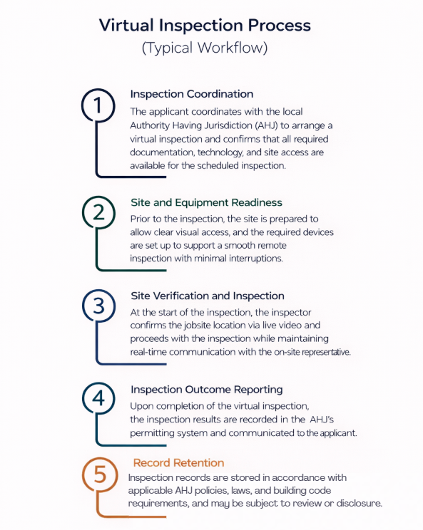
The Rest of the United States: Local Authority Control
Outside Florida, most U.S. states do not have statewide statutes that explicitly authorize or prohibit virtual inspections. Instead, acceptance is generally governed at the local level, through building department policies, administrative interpretations of adopted building codes (such as the IBC and IRC), or inspection programs adopted by individual cities or counties. National guidance, including from the U.S. Department of Energy, confirms that Authority Having Jurisdiction (AHJ) determines whether and how virtual inspections may be implemented.
Practical Impact
Because there is no uniform national rule, virtual inspections across the U.S. are typically conditional and jurisdiction-specific. Even where allowed, AHJs often restrict virtual inspections to minor work or re-inspections, exclude structural or life-safety elements, and reserve the right to require an in-person inspection at any time. As a result, in states other than Florida, virtual inspections are not automatically permitted and must be evaluated case by case with prior approval from the local Building Department
Pros
Virtual inspections reduce scheduling delays by eliminating travel and allowing faster coordination.
They lower inspection costs by minimizing time and transportation requirements.
Virtual inspections are effective for minor work, re-inspections, and clearly visible conditions.
They provide flexibility when site access, weather, or logistics make in-person inspections difficult.
In jurisdictions like Florida, virtual inspections are explicitly authorized by statute, providing regulatory clarity.
Cons / Inconvenients
Virtual inspections are not universally accepted and often require prior approval from the local AHJ.
Visibility limitations may prevent reliable verification of certain construction conditions.
Structural and life-safety inspections are commonly restricted or prohibited from being performed virtually.
Acceptance and requirements vary significantly between jurisdictions, even within the same state.
Engineers and inspectors remain fully responsible for meeting the professional standard of care, regardless of inspection method.
USEFUL ARTICLES
For guidance with your next project, explore our Plans, Calculators, Knowledge Base,
or contact us directly for site-specific support
VISIT OUR FULL PLAN STORE
Online Design Calculators
Visit Our Knowledge Base
Site specific project request
CHAT WITH A DESIGN engineer
CHAT WITH A DESIGN ENGINEER
Site specific project request
VISIT OUR FULL PLAN STORE
Online Design Calculators
Tell us how can we improve this post?
Understanding The Material Cost Saving of Using An Engineering Express Calculator
See this article to help illustrate the significant time and cost savings of accessing engineering through an Engineering Design-aid calculator to help quote and pre-engineer your projects prior to engaging with engineering firms.
Tell us how can we improve this post?
Window and Door Shimming: Code Requirements and Engineering Reality
Window and Door Shimming: Code Requirements and Engineering Reality
Improper shimming is a structural installation defect, not a cosmetic issue. It becomes most critical when there is a large gap between the window or door frame and the structural buck. If that gap is not correctly bridged, the installation cannot perform as designed—regardless of sealants or foam.
This issue is widely misunderstood, particularly regarding acceptable shim materials.
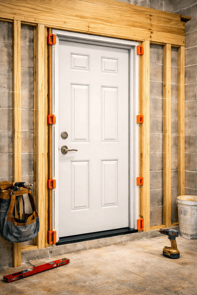
Function of Shims
Shims are load-transfer elements, not fillers. Their function is to transfer vertical and lateral loads from the window or door frame into the structural buck while maintaining the unit in proper plumb, level, and square alignment. Proper shimming also provides continuous, solid backing at fastening locations so that anchors and screws can perform as designed.
When fasteners are installed across unsupported gaps, the load path is broken. This condition leads to fastener deflection, frame distortion, operational failure, and long-term performance issues. Any fastener spanning open space constitutes a failure of structural support, regardless of the presence of foam or sealant.
Code Requirements
The IRC and IBC require that windows and doors be:
-
Installed in accordance with manufacturer instructions -
Adequately supported at bearing and attachment points -
Capable of resisting applicable design loads -
Maintained in proper alignment
Neither code prescribes shim material.
Code compliance is based on performance, not material type.
![]()
A service provided by Engineering Express®
Get FORTIFIED Certified
Learn more about how to attract more insurance companies & earn discounts on insurances for following the FORTIFIED Home Process.
Acceptable Shim Materials
Wood Shims
Wood shims are commonly used in residential construction and are acceptable when they:
-
Provide solid, continuous bearing -
Are protected from moisture exposure -
Maintain structural integrity over time
-
Wood is vulnerable to moisture absorption, shrinkage, splitting, and decay, which can compromise load transfer and frame alignment in the long term.
Plastic Shims
Plastic or composite shims are fully code-compliant and widely used in exterior window and door installations.
They provide:
-
High compressive strength -
Permanent dimensional stability -
Resistance to moisture and deterioration -
Consistent thickness for uniform bearing
-
From an engineering standpoint, plastic shims often deliver equal or superior performance compared to wood, particularly where larger gaps or moisture exposure are present.
Metal Shims
Metal shims are also code-compliant when compatible with the installed system and permitted by the manufacturer.
They are typically used for:
-
High-load conditions -
Tight dimensional tolerances -
Commercial or structural application -
Consistent thickness for uniform bearing
-
While mechanically excellent, metal shims are rarely required in wood-framed residential openings and should be used judiciously to avoid corrosion, thermal bridging, or material incompatibility.
Structural Shimming Requirements for Large Gaps
When the gap between the frame and the structural buck is significant, shimming must be continuous and load-bearing to maintain a proper load path. Large gaps cannot be addressed with spray foam, sealants, or fasteners spanning open space. Shims must fully bridge the gap and be installed at all manufacturer-required support and attachment points. Fasteners are not designed to span unsupported gaps; when they do, the load path is broken, leading to fastener deflection, loss of clamping force, and potential frame distortion. Foam and sealants do not provide structural support and cannot replace proper shimming.
Shims must fully bridge the gap and be installed at all manufacturer-required support and attachment points.
USEFUL ARTICLES
For guidance with your next project, explore our Plans, Calculators, Knowledge Base,
or contact us directly for site-specific support
VISIT OUR FULL PLAN STORE
Online Design Calculators
Visit Our Knowledge Base
Site specific project request
CHAT WITH A DESIGN engineer
CHAT WITH A DESIGN ENGINEER
Site specific project request
VISIT OUR FULL PLAN STORE
Online Design Calculators
Tell us how can we improve this post?
Building Component Design Discovery Phase And The Following Engineering Process Explained
About Engineering Express’s Building Component Design Process
Analyzing and engineering building products is complex
— But it doesn’t have to be.
With over 30 years of experience, Engineering Express has built a proven, systemized workflow that streamlines product engineering for manufacturers and the dealers who depend on it for permitting and construction.
Let’s take a closer look at the process.
Step 1: The Introductory Phase
You will agree that it’s not possible to provide a fair quote without first understanding your system and letting you select from your available options.
Engineering Express has refined this process down to a 4 hour introductory quote.
This allows us to provide you with the absolute best success plan.
What the Introducory Phase Includes
-
Scoping Call – Discuss needs and goals -
Data Collection and Organization -
Preliminary Feasibility Study To Determine Options -
Summary Report For Client Consideration
The Summary report will be used to generate a quote for step 2. You can even ‘shop it around’ for quotes from other firms adding more value to this phase.
NOTE: This phase doesn’t include any other deliverables such as answers, details or calculations. That’s next.
After we complete this phase, we will provide you with a detailed quote
that includes all options discussed and agreed upon.
Step 2: Creating The Engineering Templates
From our findings in phase 1, we will send you a full outline of the work and the detailed price quote for each step.
Our true mission is to systemize your engineering needs by creating drawing and calculation templates from the information gathered.
This will set you up for the creation of useful tools to help you quote, prepare project designs, and expedite engineering time and reduce costs.
Step 3: Creating Performance Evaluations & Site-Specific Designs
With the templates in hand, we create the deliverables you need for quoting, design, and construction.
This is typically the goal of the project which you are in touch with us every step of the way to ensure your ideal solution.
Other Amazing Possibilities
Our Amazing Calculators
Imagine putting the engineering in your hands – No calling the engineer 100 times for the perfect answer, no delays in responses, and always the perfect solution.
Our calculators allow you, your dealers, or customers to interact with the systemized calculations publicly or privately to produce the ideal design – Then quickly send that to us for rapid engineering at VIP rates
View Our Public Calculators
Learn How It Works
Our Acclaimed Plan Store
With over 700 pre-engineered plans from dozens of manufacturers for quick certification across the US, you can be assured our full-time store support staff will expedite engineer-sealed performance evaluations to your customer, allowing their designer to use them in the permitting & construction process.
We maintain the largest building product plan store in the US with great marketing and support reach for your product.
As a bonus, we include a private-labeled engineering support channel which summarizes all your customer needs – plans, calculators, site specific designs, articles, and live support into one microsite just for you.
How To Get Started With Your Building Product Evaluation
Get started on your building product design solution today.
Complete our intake form which feeds directly into our proprietary operating system EXOps – Your one stop for project quoting, management, files, and communication.
It’s custom written over years of development to best serve you.
Tell us how can we improve this post?
How To Submit A Request For An Engineering Evaluation of Doors and Other Openings For Certification
Determining Pressure Ratings For Doors (or Windows) With Alternate Components
Exterior doors exposed to weather are approved to withstand design pressures for a variety of conditions.
Sometimes, though, the door type you want to use doesn’t match the product approval.
This article explores how such a change is evaluated by an engineer to provide a certified pressure for permit.
Example of a Von Duprin panic device,
a common substation request for
door component evaluations
![]()
A service provided by Engineering Express®
Get FORTIFIED Certified
This topic also applies to the IBHS FORTIFIED program.
Learn more about how to attract more insurance companies & earn discounts on insurances for following the FORTIFIED process.
Part 1 – What Can And Can’t Change In A Door (or window) To Be Certified
These are the door (or window) components that can generally be modified
-
Door (or window) Sizes * -
Alternate Anchors (click for full article)
-
Hinges -
Locksets -
Panic Devices (sometimes) -
Glazing Infill (sometimes)

In all cases, the overall design pressure rating will be the lowest pressure of all the combined components.
Click here to read about Allowable (ASD) and Ultimate design pressure considerations.
* In the case of door (or window) sizes, for large missile impact approved products, the size cannot exceed testing. An engineer would also need to review aspect ratio and the ‘inscribed area’ to determine applicability.
Items like panic and glazing infill also must meet other criteria such as fire, egress, safety, and other factors as determined by an engineer & the architect of record.
These are the door (or window) components that can generally CANNOT be modified
-
Door (or window) Frame -
Door (or window) Internal Connections & Materials (maybe) -
Products Without Approval Or Testing -
Products Requiring Water Infiltration (click for full article)

Generally speaking, if it’s no longer the same door of if your door isn’t already approved, the process needs to start from the top in getting a Product Evaluation.
Let us take a look at your unique condition to determine applicability.
Part 2 – What Engineers Need To Perform The Evaluation
To submit a request for a site-specific evaluation approval, we need the following:
-
Product Approvals or Testing For ALL Components being used -
A Floor plan of the proposed installations showing SIZES & PRESSURES of each door/window -
Desired deliverable – letter, shop drawing, other
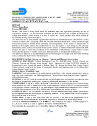
Examples of Florida and Miami Dade Product approvals, common evaluations for door and window approvals.
Part 3: How Engineering Express Can Help
Submit Your Request For Revew Now
Engineering Express will review your request to see if we are a fit.
By completing the request form, we can ensure that we capture the necessary information (explained above) to provide the best price and delivery timeframe available.
Request A Quote From Engineering Express
Are you a client of ASSA Abloy? (Ceco, Curries, Corbin Russwin, etc).
Click Here to see our Brand Channel Page.
Tell us how can we improve this post?
Understanding the 3 Types of Glazing Supports
See this article for a breakdown of the three most common types of window / door / glazing support mullions in our articles section.
Learn the difference between a mullion, supporting frame, and structural column and how they are used in a construction project.
Tell us how can we improve this post?
Glass Aspect Ratio Limitations in Florida’s High Velocity Hurricane Zone (HVHZ)
When A Glazed Opening Isn’t Exactly Square
Often times a glazing product is approved for large missile impact, but requires a field modification for size.
While the tested span cannot be exceeded and still meet the building code’s large missile impact requirements, the aspect ratio (the length to width ratio) can be altered so long as the glass area does not exceed the tested size.
The maximum aspect ratio of the length to width in glazing within the HVHZ is 5:1.
See this link to the Miami-Dade website explaining the Aspect ratio requirements.
Keep all of the Larger dimensions / Smaller diminsions below 5 so the comparative analysis will fall within the ASTM E1300 requirements.
If the aspect ratio exceeds 5 and the client wants to include it in a Florida Product Approval, then additional glass units should be tested using the requested Glass unit size.
Understanding the ‘Bounding Box’
Sometimes glazing units are not rectangular or square.
Use the below image as a guide to understanding the general theory of measuring glass unit sizes and aspect ratios for your comparative analysis.
Always seek the advice of a design professional prior to installing any shape outside of Miami-Dade or Florida Product Approval specifications.
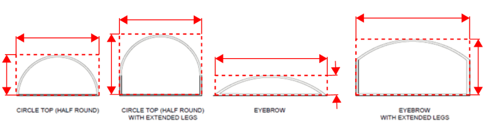
Find Approved Glazing Products
Find Florida & nationally approved glazing products for use in construction at EngineeringPlans.com.
Tell us how can we improve this post?
Understanding Fence Design: Key Considerations and Code Requirements
Fences – An Overview
Fences serve multiple purposes, from enhancing privacy and security to defining property boundaries and improving aesthetics.
However, a well-designed fence isn’t just about appearance, it must also comply with building codes to ensure safety, durability, and structural integrity.
This article explores common fence designs and the key regulations that apply to them.
Whether you’re working on a residential or commercial project, understanding these requirements will help you make sure your fence is safe, functional, and meets the latest building code standards.
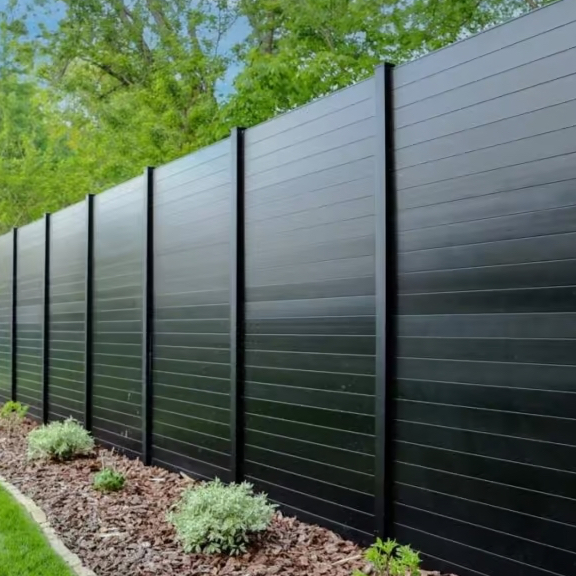
Common Fence Styles
Fences come in various designs, each serving different purposes.
Privacy fences are built to block visibility, offering seclusion for homes and businesses. They typically feature solid panels with no gaps, commonly seen in residential backyards or around commercial properties needing restricted access.
Open fences, on the other hand, provide a boundary without fully obstructing views. These include picket fences, metal bar fences, and decorative aluminum or wrought iron designs, often used in front yards, parks, or public spaces where aesthetics matter.
Chain link fences are one of the most practical and widely used fence types, valued for their durability and low cost. They are commonly used in residential areas, schools, and industrial zones where containment is needed without blocking visibility.
Ranch fences, also known as post-and-rail or split-rail fences, are designed to cover large areas efficiently. They are popular in rural settings, farms, and equestrian facilities, providing clear boundaries while maintaining an open feel.
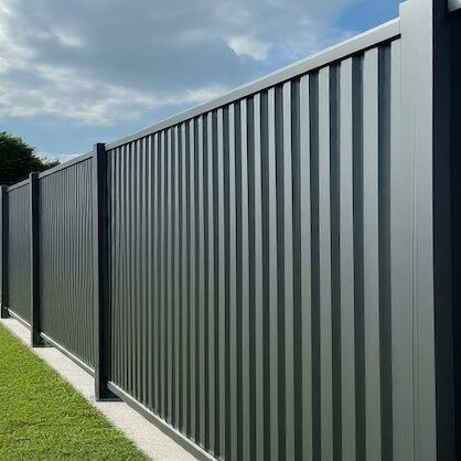
Privacy Fence
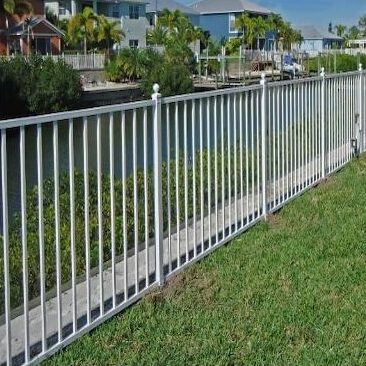
Open Fence
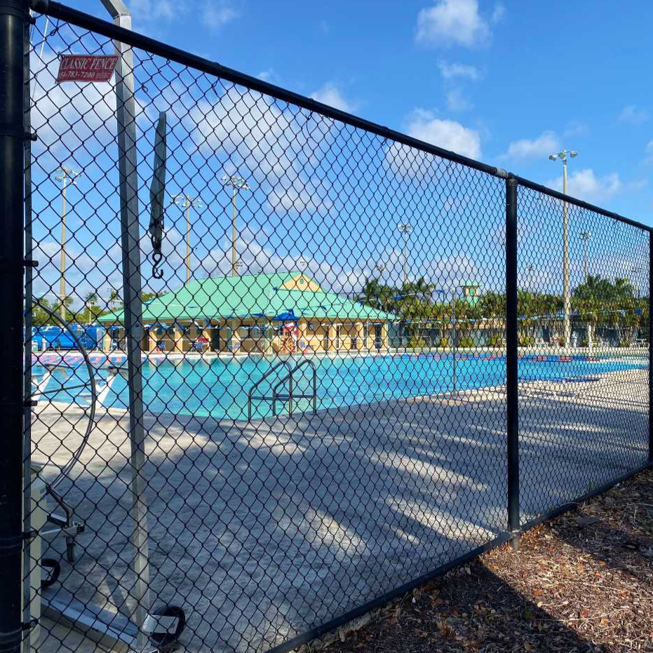
Chain Link Fence
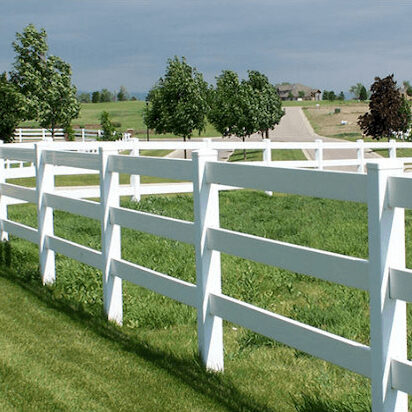
Ranch Fence
When choosing a fence, the material plays a key role in its durability, maintenance, and appearance.
There are a variety of materials to choose from, including wood, vinyl, PVC, composite, aluminum, steel, concrete, and more. Each material has its own unique benefits and is suited to different applications.
For more detailed information on which fence material is best for your specific needs, check out the article on our building product directory site EngineeringPlans.com – Plan For The Perfect Fence.
Check out our general fence plans and find the one that fits your needs.
View all pre-engineered fence plans
Need A Site-Specific Adaptation To One of Our Performance Evaluations?
Every project is unique—get a personalized fence design with our site-specific quote system.
Ensure your fence meets all requirements with a fast and accurate quote from our experts.
request your site-specific quote
Wind Resistance in Fence Design
Wind Resistance for 6 ft Fences, Simplified by FBC
Wind is one of the biggest challenges when designing a durable fence, especially in high-wind areas like Florida. Strong winds exert pressure on the structure, which can cause leaning, bending, or even complete failure if the fence isn’t properly built. The impact is even more significant on solid fences, which act as a barrier against the wind, compared to open designs that allow air to pass through.
Designing fences in high-wind zones can be tricky, requiring careful consideration of materials, post spacing, and anchoring methods. However, the Florida Building Code (FBC) provides clear guidelines to simplify the process. According to the FBC Section 1616.2.1, fences under 6 feet in height must be designed to withstand wind speeds of 115 mph. This standard simplifies the design process by setting clear requirements, ensuring fences meet safety standards without being overengineered.
“Fences not exceeding 6 feet (1829 mm) in height from grade may be designed for allowable wind speeds of 75 mph (33 m/s) fastest mile wind speed or 115 mph (40 m/s) 3-second gust.”
Florida Building Code (FBC) – Section 1616.2.1
For fences over 6 feet in height, special attention is needed to ensure they can withstand the increased wind loads, especially in high-wind areas. Taller fences experience more pressure from the wind, and factors such as the materials used, post spacing, and anchoring methods become even more critical.
The Impact of Porosity on Wind Loads
Wind effectiveness on a fence largely depends on its porosity. Porosity refers to the amount of open space or gaps within a fence that allows wind to pass through.
For example, a privacy fence with solid panels has low porosity, meaning wind pressure can build up against it, putting stress on the structure. In contrast, an open fence like a picket fence has high porosity, allowing wind to flow through the gaps, which reduces the pressure on the fence and lowers the risk of damage during strong winds.
Porosity is defined in ASCE 7, which provides guidelines on how to calculate it and its impact on wind loads. For more detailed guidance on calculating porosity and its impact on your fence design, check out our article on How to Calculate Porosity.
Fences Serving as Handrails
In certain situations, fences can also function as handrails , providing support and safety in areas where people may lean or rest against them. For example, along walkways, in public spaces, or near the edges of platforms, fences are exposed to additional pressure from individuals leaning or sitting on them.
As a result, fences used as handrails must be designed to handle higher loads to ensure their stability. Therefore, they must meet the requirements of ASCE 7-22 Section 4.5.1, which specifies that they must be able to withstand:
- • A concentrated load of 200 pounds applied at any point along the top rail.
• A distributed load of 50 pounds per linear foot across the entire length of the fence.
These load requirements are crucial to prevent the fence from failing under pressure, keeping it stable and secure whether it’s acting as a barrier or providing support.

Pool Enclosure Fence Requirements
Each year, tragic accidents occur when young children gain unsupervised access to swimming pools. Drownings and near-drownings happen in seconds, often because there wasn’t a proper barrier in place. A well-designed pool fence is one of the most effective ways to prevent these incidents, stopping children from climbing over, crawling under, or slipping through gaps. To address this risk, the Florida Building Code (FBC) has strict requirements for pool enclosures to help keep pools secure when adults aren’t around.
The Florida Building Code (FBC) Section R4502.17.1 requires all outdoor swimming pools to be enclosed by a barrier to prevent unsupervised access, particularly by young children. This barrier must be at least 48 inches high and free of any openings or design features that could allow climbing. Additionally, gates providing entry to the pool area must be self-closing and self-latching, with latches positioned at least 54 inches above the ground to keep them out of children’s reach.
In other states, this code should be followed if the local municipality does not publish a specific requirement. Always check with your local municipality for a code rule like this, or it is recommended this be followed as a minimum.
1. Barriers Without Closely Spaced Horizontal Members
For fences without horizontal members or with horizontal members spaced more than 45 inches apart, the barrier must be at least 48 inches high, with no openings that allow a 4-inch sphere to pass through. The bottom gap cannot exceed 2 inches , or 4 inches if mounted on an elevated pool structure.
2. Barriers With Closely Spaced Horizontal Members
If the fence has horizontal members spaced less than 45 inches apart, the horizontal members must be located on the pool side of the fence to prevent them from being used as a climbing aid. Additionally, any vertical spacing between pickets or slats must be no more than 1.75 inches apart to prevent footholds.
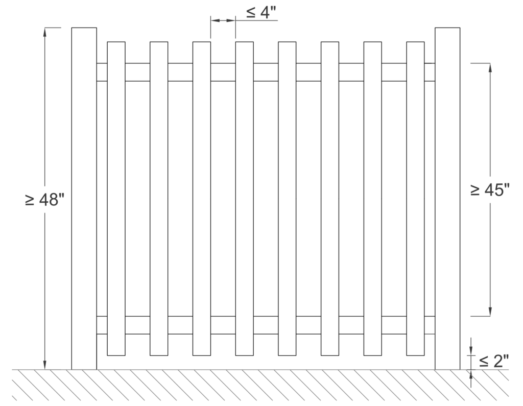
Barriers Without Closely Spaced Horizontal Members
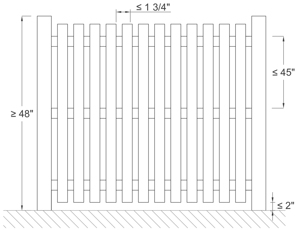
Barriers With Closely Spaced Horizontal Members
3. Chain-Link, Lattice, and Diagonal Members
• Chain-link fences must have a maximum mesh size of 2.25 inches unless fitted with slats to reduce openings to no more than 1.75 inches.
• Lattice or diagonal members must have openings no larger than 1.75 inches in width to prevent climbing.
Final Word On Fence Design
There’s long been debate on whether a fence is considered ‘properly designed’ if the fence lists (leans over) during a high wind event.
When the question was asked to the Florida Engineering Board’s Attorney, the answer came back that the design ‘is as the engineer intended’ – with the prevailing decision being whether the system after a design event caused loss of property or affected the safety of the public.
With the understanding that soil could be saturated during a design event, compaction isn’t typically mandated or measured during fence construction, and wind gusts can be above the code minimum (such as in an ASCE 7 Risk Category 1 design), it is the opinion of many design professionals that a fence may list but stay intact during a design event and be considered properly designed.
This article has covered several key requirements for fence design, but it’s important to consult your local building codes to ensure your structure meets all necessary regulations. Always reach out to a licensed engineer for expert advice and guidance tailored to your specific project.
For more detailed information and professional support on your future projects, don’t hesitate to contact us. If you have any questions or want to learn more about our services, simply get in touch—click the buttons below to get started.
Also, make sure to check out our other engineering articles for more valuable insights and tips!
For more detailed information and guidance on handling your future design projects, check out our online design calculators, contact us for site-specific projects, or reach out to us with your inquiries.
Online Design Calculators
Site specific engineering request
Contact us
Tell us how can we improve this post?
Guide To Mechanical Unit Permits and Engineering Requirements In Florida & The US
Mechanical Equipment Design – A National Requirement
Generally speaking, building codes are national in nature, but are adopted locally for unique geographic conditions.
While national codes require designing code-compliant structures during design events, areas such as South Florida take the lead on high-wind requirements for rooftop mechanical units & serve as a guide for design elsewhere.
Start Here: IBC/FBC Chapter 16
On a national level, following down to all local codes in the US is the requirements of Chapter 16- Structural Design.
This is the basis for requiring that all parts of building comply with the code – for combinations of wind, snow, seismic, and other forces.

From Chapter 16 IBC/FBC
1604.1 General
Building, structures and parts thereof shall be designed and constructed in accordance with strength design, load and resistance factor design, allowable stress design, empirical design or conventional construction methods, as permitted by the applicable material chapters.
1604.2 Strength
Buildings and other structures, and parts thereof, shall be designed and constructed to support safely the factored loads in load combinations defined in this code without exceeding the appropriate strength limit states for the materials of construction. Alternatively, buildings and other structures, and parts thereof, shall be designed and constructed to support safely the nominal loads in load combinations defined in this code without exceeding the appropriate specified allowable stresses for the materials of construction.Loads and forces for occupancies or uses not covered in this chapter shall be subject to the approval of the building official.
(as of 2023 FBC / 2021 IBC)
Down To the South Florida County Level
While each municipality in Broward have their specific forms, Broward County Board of Rules & Appeals controls all Broward Municipality requirements.
Palm Beach County municipalities each produce their own requirements, but frequently base their work on Broward County Rules.
Dade County is a mix of both, but still with rooftop equipment high-wind requirements.
Broward County Role Model City
While the rules in Broward County are all the same (and similar for other Florida Counties), this form from the City of Pompano does the best job in summarizing requirements.
It serves as a best-in-class guide for the permitting process.
The form lists the process & provides links to Broward County Applications.
How Structural Engineering Fits In
From the combination of Chapter 16 FBC & the specific inclusion of tie down requirements, both AC/generator cabinets & their mounts (stands, tie downs, ground pads, wall brackets, etc.) must be certified by a design professional to withstand code design forces.
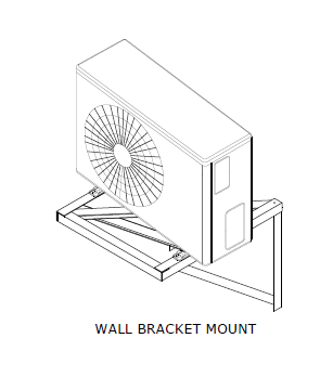
From The Pompano Form
REQUIRED PERMIT APPLICATIONS & DOCUMENTS:
Submit a completed Broward County Uniform Permit Application (Mechanical Checked) from a licensed mechanical contractor.
Submit a completed Owner / Builder Statement Affidavit, should the applicant utilize Florida Statute 489.103 Exemptions and assume responsibilities of a contractor. (Owner/Builder option is not applicable for work in Condominiums)
Submit a completed Broward County Uniform Permit Application (Building Checked) from a licensed general contractor for new installs, mini splits, or if the configuration or layout has changed.
Submit a completed Broward County Uniform Permit Application (Electrical Checked) from a licensed electrical contractor for new installs, mini splits, or if the configuration or layout has changed.
Submit a completed Zoning Compliance Permit Application from a licensed contractor for new installs, mini splits, or if the configuration or layout has changed.
If there are trees located adjacent to the work, submit a completed Tree Permit Application with Tree Protection Plan and Tree Protection Detail.
‘AHRI Certificate of Product Ratings’ page for the A/C equipment being installed.
A completed A/C Equipment Change Out form, officially called the “Broward County Uniform Data Form for Residential and Light Commercial Air Conditioning Replacements.”
-PAYING SPECIFIC ATTENTION TO THIS SECTION-
Attachments details for equipment exposed to the outside, shall be submitted in the following format:
- ‘Florida Product Approval’ or ‘Miami Dade Notice of Acceptance’ Tie Down details
— OR —
- Original signed & sealed engineer plans or documents
— OR —
- If applicable: plans & documents reviewed by a Private Provider shall be signed, dated & stamped.
Source Links
https://www.broward.org/Building/Contractors/Documents/Mechanical%20Permit%20Requirements.pdf
https://www.broward.org/Building/Forms/Pages/Building-Code-and-Permits.aspx
![]()
A service provided by Engineering Express®
Get FORTIFIED Certified
This topic also applies to the IBHS FORTIFIED program.
Learn more about how to attract more insurance companies & earn discounts on insurances for following the FORTIFIED process.
How Engineering Express Helps With Mechanical Equipment Engineering
Engineering Express exclusively provides structural designs of building products in Florida and across the US. Here are some ways we can help
We Provide Sealed Pre-Engineered Plans For Permit
We provide sealed reports for over 300 models from most all major carriers including Trane, Carrier, Daikin as well as stands & pads from manufacturers such as Diversitech & Miami Tech & dozens more
Browse Our Mechanical Equipment Plans
We Provide Site-Specific Engineering When Needed
Approved contractors gain VIP access to expedited engineering, quoting & personal project management.
Begin a quote to request your custom need & start a relationship with us.
Request A Quote For A Custom Design
Help, Help, & More Help
Use Our Free Directory of ALL Product Approvals
Browse our extensive industry Knowledge Base
See our extensive Mechanical Equipment Forces Page
Live Chat With Us
Send Us A non-project-specific message
Smart Search Miami Dade NOA, Florida Product Approvals
& certifications from other agencies all at once with our nationally acclaimed directory search tool EngineeringPlans.com.
Use an approval from an accredited agency instead of needing an engineer-sealed plan for product certification.

Use our Free Rooftop Equipment Wind Pressure Calculator to calculate pressures & forces for up to (5) rooftop units. Order certified copies for permit or compare results with your product approval or engineering plan.
Tell us how can we improve this post?
The Ultimate Guide To Creating A Window – Door Retrofit Permit Package In South Florida & Beyond
How To Apply For A Retrofit Window-Door-Garage Door Permit In South Florida & Beyond
Dade, Broward & Palm Beach Counties have adopted a unique set of rules for permitting window and door replacements (alteration level 1). Other coastal counties across the US are catching on, so the process applies when needed.
While there are variations between cities, counties, & states, these requirements are similar.
Alteration Level 1 Defined: FBC/IBC existing building Section 602.1
Level 1 alterations include the removal and replacement or the covering of existing materials, elements, equipment, or fixtures using new materials, elements, equipment, or fixtures that serve the same purpose.
The Approval Process, Step By Step
(click on each for more information)
1) Provide Product Approvals of each unit being installed
If you don’t already have product approvals, search EngineeringPlans.com & download the product approvals you need.
You can also search Google or the Florida or Miami approval websites. EngineeringPlans also provides links to the source pages for quicker access.
The product approval is a plan that specifies the design pressure of the product for a given size, substrate, and glazing.
You’ll need to identify the size and parts you’re using and identify that limiting pressure for the permit documents.
Product Approval Markup Example
In the example below, we are using PGT PW7620A non-impact fixed window.
We’re looking for the limiting design pressure for a 72″ X 36″ window (2,3) using 3/16″ annealed glass (1)
After reviewing the approval plans, we find the limiting pressure is +-38.3psf as seen in the below markup.
We now have a design pressure for this window to compare to our site-specific condition for permit.
The municipality would likely want a markup similar to this to illustrate compliance.
(NOTE: This product example is NOT impact approved and a large missile impact system would need to cover the opening).
What to submit with your permit
In addition to the product approval plan set, you’ll want to submit the entire approval package.
For Miami Dade, that’s the entire NOA document that’s downloaded with the plans.
For Florida Product Approvals, find & print the cover page & submit that with the approval plans. The image to the right is the page they are looking for. (click for larger image)
Important to note, the approval documents do NOT have to be re-sealed by an engineer.
See this article that explains more.
2) Provide a signed and sealed plan from a PE or architect of all locations & pressures
A window / door retrofit plan is simply an overhead view of the structure which roughly locates each opening.
Somewhere within the plan or as an attached schedule, opening marks are called out along with sizes, pressures, and ideally the product approval being used as per above #1.
The good news is it doesn’t have to be to scale or drawn by an expert – you can do it!
Use this FREE TOOL to draw and save your sketch
Examples & Tools To Help
Click to see a small house example
Here we see a simple sketch, drawn by hand, using our simple tool, or by a CAD software program.
All that’s needed is to identify the openings being modified and their rough location in the building.
Anything close to a building corner is zone 5 (see this article which explains wall zones)
The Window & Door schedule needs to contain the following information.
Sample window/door schedule charts are found in the resources below for various municipalities.
1 – The ‘mark’ which comes from the house plan
2 – The quantity of this item
3 – The product size
4 – The ASCE 7 wind pressure zone
5 – The name/description of the product being installed
6 – The FL / Miami Dade product approval number
7 – The Design Pressures calculated for that opening (see resources below)
NOTE: The Approved Pressures must be greater or equal to the site-specific Design Pressures. This is the whole point of this exercise.
Click to see a larger condo example
Projects over 30′ height in South Florida all require a site specific plan sealed by a PE or or Architect.
While Engineering Express can assist you in creating this, it’s always quicker and less expensive if you create the drawing yourself.
You can use this tool to create the image below and submit to us.
See the small house example above for more information on the drawing requirements.
Click to see what the Village of N Palm Beach publishes as a good example
The Village of North Palm Beach publishes this example to illustrate an acceptable window-door plan and schedule.
It follows most all of South Florida requirements (see more municipality links in the resources below).
2) OR provide an unsealed plan and a ‘worst case’ design pressure chart sealed by a PE or Architect *
After creating your own sketch or using our online sketch tool, the next step is to determine your ‘worst case’ design pressures.
Engineering Express sells pre-engineered design charts for your wind speed & exposure (get those from your building department or see the notes in one of our charts).
Determine whether you’re in an interior zone 4 or more critical end zone 5. If in doubt use zone 5 (more critical).
Purchasing Certified Wind Pressures For Your Project
Engineering Express provides three resources for quickly obtaining certified wind pressures for your project.
Contact us in our online chat if you have questions.
-
ASCE7 C&C Wall Loads Calculator
$75.00 – $125.00Price range: $75.00 through $125.00
View
-
Wind Pressure Charts For Windows – Doors – Shutters
$25.00 – $30.00Price range: $25.00 through $30.00
or ( 2.5 Tokens – 3 Tokens )
View
-
Wind Pressure Charts For Garage Doors & Large Openings
$30.00
or ( 3 Tokens – 3 Tokens )
View
* Some municipalities in Broward County will accept an unsealed sketch along with the use of this ‘worst case’ wind pressure chart as it is described. Learn more here.
Engineering Express only supports clients that purchase our sealed wind pressure charts as shown above. They provide better answers and ensure an engineer is able to answer questions and assist with use as applicable.
Broward County ‘worst case’ wind load chart – see municipality for applicability (2023 edition).
Click for larger image.
3) IF the structure is taller than 30′ or multifamily, a site specific plan (Option 2) is required
This plan follows the ‘larger condo example’ from option 2 above.
It does need to be sealed by a PE or Architect, but you can use this tool to help create the plan and create your own window and door schedule to bring down cost and speed up processing.
NOTE: Some municipalities use 30′ as the total roof height, while others the mean roof height. See this article for more & ask your municipality before submitting for engineering & permintting.
See these requirements visually (flowchart)
This flowchart has been adopted from the unincorporated Broward County Application Information Packet (2020)
Proceed to next steps / permitting
If you don’t already have product approvals, search EngineeringPlans.com & download the product approvals you need.
You can also search Google or the Florida or Miami approval websites. EngineeringPlans also provides links to the source pages for quicker access.
The product approval is a plan that specifies the design pressure of the product for a given size, substrate, and glazing.
You’ll need to identify the size and parts you’re using and identify that limiting pressure for the permit documents.
Product Approval Markup Example
In the example below, we are using PGT PW7620A non-impact fixed window.
We’re looking for the limiting design pressure for a 72″ X 36″ window (2,3) using 3/16″ annealed glass (1)
After reviewing the approval plans, we find the limiting pressure is +-38.3psf as seen in the below markup.
We now have a design pressure for this window to compare to our site-specific condition for permit.
The municipality would likely want a markup similar to this to illustrate compliance.
(NOTE: This product example is NOT impact approved and a large missile impact system would need to cover the opening).
What to submit with your permit
In addition to the product approval plan set, you’ll want to submit the entire approval package.
For Miami Dade, that’s the entire NOA document that’s downloaded with the plans.
For Florida Product Approvals, find & print the cover page & submit that with the approval plans. The image to the right is the page they are looking for. (click for larger image)
Important to note, the approval documents do NOT have to be re-sealed by an engineer.
See this article that explains more.
A window / door retrofit plan is simply an overhead view of the structure which roughly locates each opening.
Somewhere within the plan or as an attached schedule, opening marks are called out along with sizes, pressures, and ideally the product approval being used as per above #1.
The good news is it doesn’t have to be to scale or drawn by an expert – you can do it!
Use this FREE TOOL to draw and save your sketch
Examples & Tools To Help
Click to see a small house example
Here we see a simple sketch, drawn by hand, using our simple tool, or by a CAD software program.
All that’s needed is to identify the openings being modified and their rough location in the building.
Anything close to a building corner is zone 5 (see this article which explains wall zones)
The Window & Door schedule needs to contain the following information.
Sample window/door schedule charts are found in the resources below for various municipalities.
1 – The ‘mark’ which comes from the house plan
2 – The quantity of this item
3 – The product size
4 – The ASCE 7 wind pressure zone
5 – The name/description of the product being installed
6 – The FL / Miami Dade product approval number
7 – The Design Pressures calculated for that opening (see resources below)
NOTE: The Approved Pressures must be greater or equal to the site-specific Design Pressures. This is the whole point of this exercise.
Click to see a larger condo example
Projects over 30′ height in South Florida all require a site specific plan sealed by a PE or or Architect.
While Engineering Express can assist you in creating this, it’s always quicker and less expensive if you create the drawing yourself.
You can use this tool to create the image below and submit to us.
See the small house example above for more information on the drawing requirements.
Click to see what the Village of N Palm Beach publishes as a good example
The Village of North Palm Beach publishes this example to illustrate an acceptable window-door plan and schedule.
It follows most all of South Florida requirements (see more municipality links in the resources below).
Here we see a simple sketch, drawn by hand, using our simple tool, or by a CAD software program.
All that’s needed is to identify the openings being modified and their rough location in the building.
Anything close to a building corner is zone 5 (see this article which explains wall zones)
The Window & Door schedule needs to contain the following information.
Sample window/door schedule charts are found in the resources below for various municipalities.
1 – The ‘mark’ which comes from the house plan
2 – The quantity of this item
3 – The product size
4 – The ASCE 7 wind pressure zone
5 – The name/description of the product being installed
6 – The FL / Miami Dade product approval number
7 – The Design Pressures calculated for that opening (see resources below)
NOTE: The Approved Pressures must be greater or equal to the site-specific Design Pressures. This is the whole point of this exercise.
Projects over 30′ height in South Florida all require a site specific plan sealed by a PE or or Architect.
While Engineering Express can assist you in creating this, it’s always quicker and less expensive if you create the drawing yourself.
You can use this tool to create the image below and submit to us.
See the small house example above for more information on the drawing requirements.
The Village of North Palm Beach publishes this example to illustrate an acceptable window-door plan and schedule.
It follows most all of South Florida requirements (see more municipality links in the resources below).
After creating your own sketch or using our online sketch tool, the next step is to determine your ‘worst case’ design pressures.
Engineering Express sells pre-engineered design charts for your wind speed & exposure (get those from your building department or see the notes in one of our charts).
Determine whether you’re in an interior zone 4 or more critical end zone 5. If in doubt use zone 5 (more critical).
Purchasing Certified Wind Pressures For Your Project
Engineering Express provides three resources for quickly obtaining certified wind pressures for your project.
Contact us in our online chat if you have questions.
-
ASCE7 C&C Wall Loads Calculator
$75.00 – $125.00Price range: $75.00 through $125.00
View
-
Wind Pressure Charts For Windows – Doors – Shutters
$25.00 – $30.00Price range: $25.00 through $30.00
or ( 2.5 Tokens – 3 Tokens )
View
-
Wind Pressure Charts For Garage Doors & Large Openings
$30.00
or ( 3 Tokens – 3 Tokens )
View
* Some municipalities in Broward County will accept an unsealed sketch along with the use of this ‘worst case’ wind pressure chart as it is described. Learn more here.
Engineering Express only supports clients that purchase our sealed wind pressure charts as shown above. They provide better answers and ensure an engineer is able to answer questions and assist with use as applicable.
Broward County ‘worst case’ wind load chart – see municipality for applicability (2023 edition).
Click for larger image.
This plan follows the ‘larger condo example’ from option 2 above.
It does need to be sealed by a PE or Architect, but you can use this tool to help create the plan and create your own window and door schedule to bring down cost and speed up processing.
NOTE: Some municipalities use 30′ as the total roof height, while others the mean roof height. See this article for more & ask your municipality before submitting for engineering & permintting.
This flowchart has been adopted from the unincorporated Broward County Application Information Packet (2020)
Proceed to next steps / permitting
Next Steps & Other Considerations
So you made it through the window & door retrofit plan-schedule process… But wait, there’s more:
About Window & Door Buck Requirements
Sometimes building departments require wood buck engineering & inspection when retrofitting windows & doors.
The theory behind bucks is they need to be as strong as the anchorage of the windows being installed.
Engineering Express provides both signed & sealed 1X & 2X wood buck general plans for purchase to use in permitting. Click the links below to access them & see plan samples before purchase.
-
1X Wood Buck Installation Certification Plan
$160.00 – $220.00Price range: $160.00 through $220.00
or ( 16 Tokens – 22 Tokens )
View -
2X Wood Buck Installation Certification Plan
$160.00 – $220.00Price range: $160.00 through $220.00
or ( 16 Tokens )
View
A Word About Egress
It must be mentioned that all rooms must have a means of egress. This rule must be adhered to when retrofitting windows.
Simply put, rooms such as bedrooms need 2 means of escape in the event one is blocked.
Building departments will look at these plans to make sure there’s proper egress for all rooms.
You can read more about egress here.
Mullions & Transoms – A Closer Look
A structural mullion separates two systems in an opening.
This can be between two windows, doors with sidelites, transoms, or multiple configurations.
Mullions do not require product approval necessarily, but may manufacturers provide mullions with approvals for their windows and doors.
If an engineer designs a mullion without approval, it needs to meet the standard of the main frame, not of the windows. Typically this means a more critical deflection requirement.
Mullions need to be properly fastened to handle all wind, impact, and cyclical loading.
A design professional should be contacted if there is not product approval for a mullion meeting your design criteria.
How to determine wind loads on mullions
Per ASCE 7 commentary section 26.2, A mullion may receive wind from several cladding panels. In this case, the effective wind area is the area associated with the wind load that is transferred to the mullion.
This means you find the area of wind that acts on the mullion to determine it’s design pressure.
This article goes into more detail regarding mullion design.
About Garage Doors & Large Openings
The difference between a window and garage door is the size of the opening.
Large openings such as garage doors or large windows have by calculation a lower design pressure by code.
Separate engineer-sealed charts for garage door wind pressures are available for purchase to assist with permitting larger openings which can be found here
Broward County Garage Door Wind Chart
Broward County publishes Formal Interpretation #24 which provides this ‘deemed to comply’ wind chart. As you can see below, there are lower pressures for garage door sizes than smaller openings. In some situations, this chart can be referenced for permit in lieu of a sealed engineering plan chart.
On To Permitting
Combine your product approval documents, house sketch, window & door schedule, and sealed engineering charts / calculator with your window door retrofit permit application to your municipality for processing.
Application details vary per municipality & are outside the scope of this guide.
A word about digital vs physical (paper) applications
Some municipalities in the US still use paper copies. For certified engineering documents other than product approvals, this means original, embossed or ink sealed paper – NOT PHOTOCOPIES.
Digital copies are encrypted signatures that have third-party validation to ensure they are valid. They can be shared but not modified. Many contain limitations of use such as a time frame or zip code restriction.
For more information on digital & hand sealed plans, see this article.
Sometimes building departments require wood buck engineering & inspection when retrofitting windows & doors.
The theory behind bucks is they need to be as strong as the anchorage of the windows being installed.
Engineering Express provides both signed & sealed 1X & 2X wood buck general plans for purchase to use in permitting. Click the links below to access them & see plan samples before purchase.
-
1X Wood Buck Installation Certification Plan
$160.00 – $220.00Price range: $160.00 through $220.00
or ( 16 Tokens – 22 Tokens )
View -
2X Wood Buck Installation Certification Plan
$160.00 – $220.00Price range: $160.00 through $220.00
or ( 16 Tokens )
View
It must be mentioned that all rooms must have a means of egress. This rule must be adhered to when retrofitting windows.
Simply put, rooms such as bedrooms need 2 means of escape in the event one is blocked.
Building departments will look at these plans to make sure there’s proper egress for all rooms.
You can read more about egress here.
A structural mullion separates two systems in an opening.
This can be between two windows, doors with sidelites, transoms, or multiple configurations.
Mullions do not require product approval necessarily, but may manufacturers provide mullions with approvals for their windows and doors.
If an engineer designs a mullion without approval, it needs to meet the standard of the main frame, not of the windows. Typically this means a more critical deflection requirement.
Mullions need to be properly fastened to handle all wind, impact, and cyclical loading.
A design professional should be contacted if there is not product approval for a mullion meeting your design criteria.
How to determine wind loads on mullions
Per ASCE 7 commentary section 26.2, A mullion may receive wind from several cladding panels. In this case, the effective wind area is the area associated with the wind load that is transferred to the mullion.
This means you find the area of wind that acts on the mullion to determine it’s design pressure.
This article goes into more detail regarding mullion design.
The difference between a window and garage door is the size of the opening.
Large openings such as garage doors or large windows have by calculation a lower design pressure by code.
Separate engineer-sealed charts for garage door wind pressures are available for purchase to assist with permitting larger openings which can be found here
Broward County Garage Door Wind Chart
Broward County publishes Formal Interpretation #24 which provides this ‘deemed to comply’ wind chart. As you can see below, there are lower pressures for garage door sizes than smaller openings. In some situations, this chart can be referenced for permit in lieu of a sealed engineering plan chart.
Combine your product approval documents, house sketch, window & door schedule, and sealed engineering charts / calculator with your window door retrofit permit application to your municipality for processing.
Application details vary per municipality & are outside the scope of this guide.
A word about digital vs physical (paper) applications
Some municipalities in the US still use paper copies. For certified engineering documents other than product approvals, this means original, embossed or ink sealed paper – NOT PHOTOCOPIES.
Digital copies are encrypted signatures that have third-party validation to ensure they are valid. They can be shared but not modified. Many contain limitations of use such as a time frame or zip code restriction.
For more information on digital & hand sealed plans, see this article.
Remember The Floor Plan
Many Municipalities require a plan of the building illustrating the location, type, wind pressures, & product approvals being installed.
Engineering Express has a free tool that allows you to draw these floor plans.
You can also retain the services of MySitePlan.com to draw elevations, floor plans, & site plans for you.
We can also quote any project to include these drawings for you as described in STEP 3:
Tools To Help
Free Drawing Tool
Custom Quote
Resources
Links to South Florida City-County Requirements & Resources
Here is a list of notable collected web pages municipalities in South Florida have published to document & explain this process.
Other municipalities researched were found to have similar or no resources.
Always contact the municipality you are working in to obtain the latest requirements, as they frequently change without notice!
BROWARD COUNTY
Broward County Window & Door Schedule Form (fillable)
DADE COUNTY
Miami Dade Window-Door-Shutter Help Page
Dade Window Replacement Requirements
Dade Window-Door Schedule Example
North Miami Door-Window-Shutter Checklist
Homestead Window-Door-Shutter Checklist
Miami Beach Window-Door Inspection Notice
PALM BEACH COUNTY
North Palm Beach Window-Door Form with Example
Boca Raton Window-Door Replacement Form
Useful Reources – Videos -Courses
Visit our Wind Page for an overview of wind design
Window Door Pressure Charts For Purchase (multiple options)
Garage – Large Opening Door Charts for Purchase
Use our Floor Plan Sketch Tool
1X Wood Buck Plan For Purchase
2X Wood Buck Plan For Purchase
Visit EngineeringPlans.com to easily find & download product approvals.
Take Free Glazing Courses
Learn everything from installation, ordering, accessories & more in these free courses sponsored by LearnGlazing.com.
Watch our window & door installation video
Here’s another helpful retrofit video for older homes
Final Notes About This Process
NOTE: We highly recommend consulting with a licensed professional experienced in storm wind design. Impact & cyclical pressures can only be certified by testing, and breaches during a storm can affect lives, property, and the safety of surrounding homes.
We’re here to help. reach us on our Online Chat, email [email protected], fill out our Contact Us form, call 954-354-0660, or request a quote for custom & site-specific work.
Our Opinion about ‘Worst Case’
This is just our opinion. Please consult with your designer and building official as their opinion may vary.
Many municipality webistes have used the words ‘worst case’ to identify the highest possible pressure for an opening.
In theory, the smallest opening in a building corner has the ‘worst’ pressure (zone 5, 10sqft or less). If in doubt, use this number.
But many municipality ‘worst case’ forms still show interior and exterior zones 4 & 5, various tributary area, and show various roof heights, leaving ‘some’ interpretation of their worst case to the user.
It’s our opinion if a contractor is qualified enough to estimate those items, then ‘worst case’ must mean the largest design pressure value if in doubt. BUT, if qualified to determine ‘simple’ values as described herein (or are they really qualified to begin with), then worst case is the worst case if in doubt of two options.
So if at all in doubt, use a HIGHER mean roof height, LOWER opening size, and wind ZONE 5 to find the HIGHEST design pressure.
There’s also wind speed (governed by the municipality) and ASCE 7 Exposure Category – anything near the coast is exposure D if in doubt. Otherwise, use Exposure’ C’ in Dade, Broward, and Palm Beach.
Please, ask us if you have questions – We’re here to help!
Here is a list of notable collected web pages municipalities in South Florida have published to document & explain this process.
Other municipalities researched were found to have similar or no resources.
Always contact the municipality you are working in to obtain the latest requirements, as they frequently change without notice!
BROWARD COUNTY
Broward County Window & Door Schedule Form (fillable)
DADE COUNTY
Miami Dade Window-Door-Shutter Help Page
Dade Window Replacement Requirements
Dade Window-Door Schedule Example
North Miami Door-Window-Shutter Checklist
Homestead Window-Door-Shutter Checklist
Miami Beach Window-Door Inspection Notice
PALM BEACH COUNTY
North Palm Beach Window-Door Form with Example
Boca Raton Window-Door Replacement Form
Loxahatchee Window Door Application Process with examples
Town of Palm Beach Shutter-Window-Door Retrofit Guidelines
Visit our Wind Page for an overview of wind design
Window Door Pressure Charts For Purchase (multiple options)
Garage – Large Opening Door Charts for Purchase
Use our Floor Plan Sketch Tool
1X Wood Buck Plan For Purchase
2X Wood Buck Plan For Purchase
Visit EngineeringPlans.com to easily find & download product approvals.
Take Free Glazing Courses
Learn everything from installation, ordering, accessories & more in these free courses sponsored by LearnGlazing.com.
View All Courses
https://youtu.be/k8Hw-qSlm00?si=JemGFI_wN5qH_Hvi
Watch our window & door installation video
Here’s another helpful retrofit video for older homes
NOTE: We highly recommend consulting with a licensed professional experienced in storm wind design. Impact & cyclical pressures can only be certified by testing, and breaches during a storm can affect lives, property, and the safety of surrounding homes.
We’re here to help. reach us on our Online Chat, email [email protected], fill out our Contact Us form, call 954-354-0660, or request a quote for custom & site-specific work.
Our Opinion about ‘Worst Case’
This is just our opinion. Please consult with your designer and building official as their opinion may vary.
Many municipality webistes have used the words ‘worst case’ to identify the highest possible pressure for an opening.
In theory, the smallest opening in a building corner has the ‘worst’ pressure (zone 5, 10sqft or less). If in doubt, use this number.
But many municipality ‘worst case’ forms still show interior and exterior zones 4 & 5, various tributary area, and show various roof heights, leaving ‘some’ interpretation of their worst case to the user.
It’s our opinion if a contractor is qualified enough to estimate those items, then ‘worst case’ must mean the largest design pressure value if in doubt. BUT, if qualified to determine ‘simple’ values as described herein (or are they really qualified to begin with), then worst case is the worst case if in doubt of two options.
So if at all in doubt, use a HIGHER mean roof height, LOWER opening size, and wind ZONE 5 to find the HIGHEST design pressure.
There’s also wind speed (governed by the municipality) and ASCE 7 Exposure Category – anything near the coast is exposure D if in doubt. Otherwise, use Exposure’ C’ in Dade, Broward, and Palm Beach.
Please, ask us if you have questions – We’re here to help!
LEARN MORE – BROWSE OUR WINDOW & DOOR KNOWLEDGE BASE
Browse dozens of articles on wind & wind-related design in our extensive database.
Visit our ENTIRE Knowledge Base
Tell us how can we improve this post?
How To Calculate Porosity of a Louver – Sign – Fence Per ASCE 7
Porosity – How ‘Open’ A Surface Is – Explained
The porosity of open structures is defined in ASCE-7 standard under ‘open signs’ (chapter 29, as of ASCE 7-22).
This standard explains that the permeable (wind) porosity of a surface isn’t always equivalent to the calculated visual porosity.


Left: mechanically articulating louvers that can reach a porosity greater than 50%.
Top: Open fence, similar to an open sign.
The actual porosity should always be determined by a design professional, but here’s a guide.
ASCE 7 figure 29.3-1 note 2 points out two significant elements relating to porosity:
1 – Signs [and similar surfaces since mother nature doesn’t know the difference] less than (<) 30% open, porosity shall be permitted to be multiplied by the reduction factor
If Porisity < 30% open, Porisity = (1-(1-∈)^1.5)
where ∈ = the ratio of solid area to gross area.
For Example, for a surface 25% visually open (75% solid) : (1-(1-0.75)^1.5) = 0.875 or 87.5% solid for wind calculations.
2 – For open surfaces >= 30% open, the porosity calculation shall be taken as the visual (see-thru) calculation.
However, one must also consider the accumulation of debris, ice & snow on the surface in question when thinking of porosity for wind.
There are additional items to consider such as where the resultant force acts normal to the face or normal at a distance from the geometric center toward the windward edge (note 3 case A, B) or case C which goes further into analysis in ASCE 7 Chapter 29 which we encourage seeking professional assistance on in this porosity determination.
Fence Porosity – A Case Study
Take for example a fence or railing that is required to be 75% open (such as in these Lighthouse Point FL Building Code Amendments & many similar along the coastlines).
This porosity value is also frequently seen in the requirement of a barrier to be designed such that it resists a 4″ sphere.
The Porosity Calculation
Take for example the use of 3/4″ pickets and a 2″ railing/fence post to reject a 4″ sphere.
If the desired 75% porosity calculation is required for view-thru, using these values,

If this calculation came to be less than 30%, the above calculation would need to be used to determine the wind porosity which would differ from the visual porosity.
What To Do Next
Once the porosity of an opening is calculated, one must use ASCE-7 to determine the net force on a surface.
That is performed through a series of calculations in ASCE 7 Chapter 29 from the formula
F = qz * Kd * Gcf * Af
The review of this formula is beyond the scope of this article, but there are a few takeaways:
1 – qz is the force at height ‘z’ – meaning the higher the installation on a building (such as on a rooftop), the larger the force.
2 – CF – This is a force coefficient which varies depending on the type of surface the wind is flowing through.
> Interesting to note that flat-sided members yield a higher value of Cf (and consequently a larger force F) than rounded members which follow a Cf calculation based on porosity and shape as described in ASCE 7-22 Figures in 29.4.
Also, calculation of wind force (F) is performed normal (perpendicular) to the surface.
It is clear that an experienced design professional is needed to accurately account for all of these factors and variables.
Help Getting These Forces
You can purchase an engineer-certified, pre-engineered performance evaluation for permit that have tables which convert wind speed to pressure for a variety of situations. There is a free sample available for inspection before purchase.
We also have an online calculator that provides more precise answers and can help with the design. Find the wind speed-to-pressure calculator by clicking here.
Consequences Of Improper Louver Porosity Calculations
This article focuses on the calculated porosity of open louvers (surfaces) to resist uplift.
However, a prudent design would consider the need to lock louvers in the open position and for mechanical failures that could compromise pergolas.
Also, something called ‘continuous load path’ is equally as important – all the links of the chain need to be considered.
For a proper design, one must review the column base, head, and all remaining connections and elements.
We leave you with this video of an unknown pergola failure caught by a security cam of a failure in relatively low storm winds.
Engineering Express® can help you with all your louver, fence, railing, sign and gate needs using a variety of our state of the art resources. Browse our Online Store for pre-engineered plans, browse our expanding array of online calculators, or request a quote for a site-specific project in any of the 40+ states to which we are licensed.
Contact us to discuss your design needs and work through porosity considerations for your product or project.
Tell us how can we improve this post?
How To Determine Uplift Reactions For Canopies-Carports-Pergolas
Canopies & Wind Uplift – An Introduction
First, Understand This
A backyard canopy or pergola, trellis, or a lightweight sunroom/screen room attached to the back of your house are of relatively very little weight and are typically lighter in construction than the structure to which they are attached to.
Also, consider that a house wall continuously supports a roof, whereas a canopy is supported only at the corners or widely spaced posts.
These factors create the critical uplift forces on canopies resulting from wind.
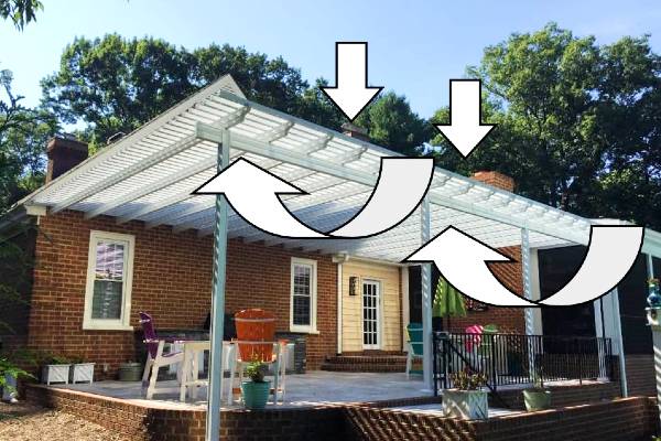
Uplift from wind puts instant, magnified forces on post connections at the head & base connection, as well as the foundation itself.
ASCE 7 contains expanded sections on how to handle these forces. More about the expanded sections of carports & canopies in the latest ASCE 7 code can be found from this article.
There’s also the question of porosity – Many think that something 50% open is 50% porous – but wind doesn’t always act that way. Read why.
Wind Uplift Design
So how does one design for uplift for a lightweight carport or canopy?
Understand this is a simplified analysis which a licensed professional must review before use. There are other forces in play – factored loads, snow, seismic, and heave to name a few which all have to be considered. But if you’re looking for a starting point, read on.
1 – After subtracting for dead loads (the self-weight of the structure), a designer must consider the net uplift force on the canopy/overhang.
The net uplift is the gross total uplift minus the gravity loads.
2- Then, consider the ‘tributary’ or ‘contributing’ area of the wind uplift force on each component it acts upon.
Take for example a host supported 3-post canopy as per this illustration:
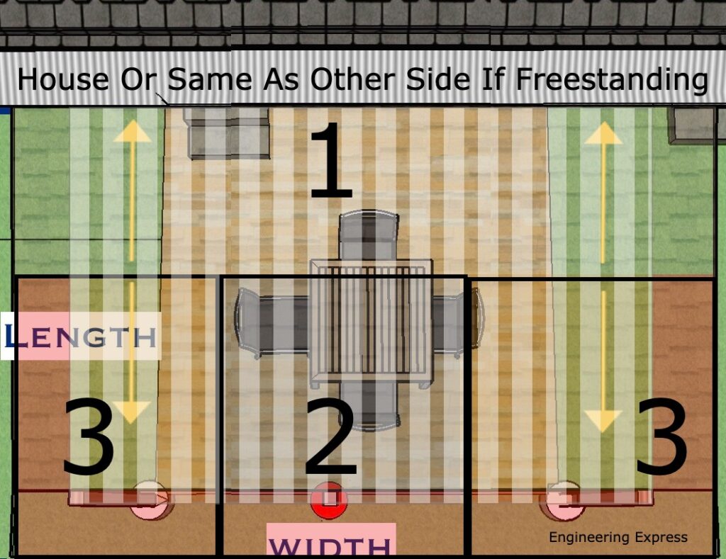
The tributary area on each outer post (area 3) is (1/2 the span (length) projection + the outer overhang) * (1/2 the column span width + the side overhang tributary area).
The tributary area on the center post (area 2) is (1/2 the span (length) projection + the outer overhang) * (1/2 the distance to the left column + 1/2 the distance to the right column).
The rest of the tributary area (area 1) goes to the main residence which is handled by the host structure connection.
In the case of a freestanding canopy/pergola, repeat the process for areas 2 & 3 for area 1.
To determine the net uplift force on each post, multiply each post’s tributary area by the net uplift force per square foot.
Determining The Net Uplift Force
Again, this is something for a design professional to assist with as many factors determine this (such as topography, exposure, risk category, among others).
This generally involves finding the applicable wind velocity and converting that speed into a wind force. We have another article that dives deeper on this topic.
Uplift Resistance – Not As It Seems
One might think the weight of the concrete/foundation needed to resist the uplift force is the answer, but there has to be a Factor of Safety acting against this force.
Concrete generally weighs 150 pounds per cubic foot.
But, the weight of concrete underwater (think rain during a storm & the soil becoming saturated) is 62.4lb/cuft less (the weight of water). This means concrete only weighs 150-62.4 = 87.6lb which is roughly 60% of the concrete weight.
There are other forces that help such as additional and factored loads, soil skin friction, connected or overtopping slabs, pavers & ground finishes that design professionals consider, but this gives you a general starting point for your design.
There are code references and examples that point to a 1.5 safety factor which consideres these factored loads. Most important to understand that there’s also a lateral (sideways) force that has to be resisted as well, to avoid footings from leaning over in high winds.
These footings can get large fast!
One must also consider frost heave in determining the depth of footings.
Other Helpful Information
Other accessories such as ground anchors, sonotube column wraps, cables, & other devices can creatively be used to help resist uplift forces.
Reinforcing steel may also be required in concrete footings. See also our footing steel requirements article to determine if steel reinforcing is required in your uplift footing.
You can purchase an engineer-certified, pre-engineered performance evaluation for permit that have tables which convert wind speed to pressure for a variety of situations. There is a free sample available for inspection before purchase.
We also have an online calculator that provides more precise answers and can help with the design. Find the wind speed-to-pressure calculator by clicking here.
More precisely to your needs, our private calculators such as our footing uplift calculator interactively designs your ideal footing for your situation. It’s available to active VIP clients after training.
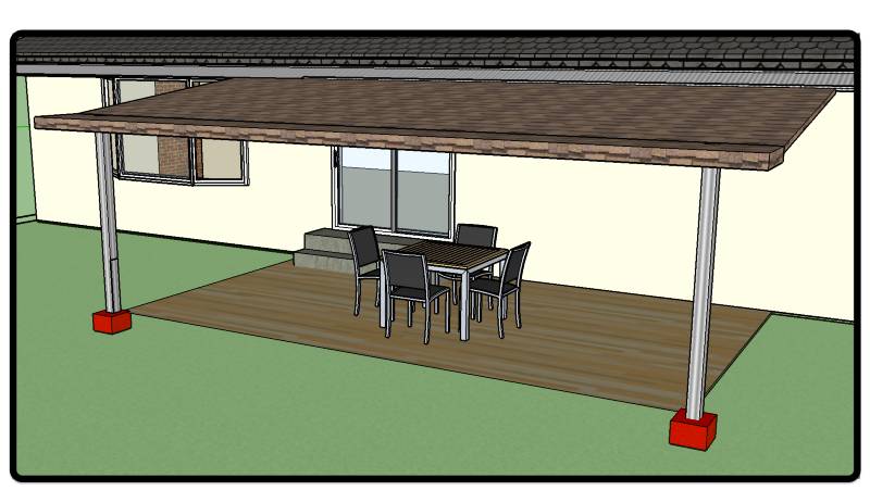
Consequences of Wind Uplift
This article focuses on the resisting weight to hold down canopies & pergolas.
But something called ‘continuous load path’ is equally as important – all the links of the chain need to be considered.
For a proper design, one must review the column base, head, and all remaining connections and elements. Engineering Express can assist you by reviewing your needs in a free quote for approved contractors & manufacturers.
We leave you with this video of a pergola failure caught by a security cam of a failure in relatively low storm winds.
Tell us how can we improve this post?
What is a delegate engineer and what are their responsibilities
What is a Delegate Engineer?
A Delegate Engineer is a licensed Professional Engineer (PE) entrusted with a defined scope of work on a project. Acting as the engineer of record for that scope in particular, they are responsible for producing, signing, and sealing their own drawings and calculations.
They must also coordinate closely with the overall building Engineer of Record (EoR) to ensure their design is safe, code-compliant, and fully integrated into the overall project. Delegate engineering must be approved by the EoR for the project.
In essence, the delegate engineer is the specialist whose expertise ensures critical portions of a project are delivered with precision and accountability.
Do Delegate Engineers Differ Between States?
While there may be slight variations in specific requirements or regulations between states, a delegate engineer’s core duties and qualifications are likely to remain similar regardless of location.
These differences are usually related to licensing requirements and industry practices based on the respective state.
What is an EoR and what is their role?
The Engineer of Record is a professional engineer who is officially responsible for the design, analysis, or evaluation of a particular engineering project as a whole (such as the primary structure).
The EoR typically oversees the delegated engineering aspects of a project, ensuring that they meet applicable codes, standards, and specifications.
These include design oversight, code compliance per location, quality assurance, coordination, documentation, permitting approval, and construction support. Sometimes Architects of Record serve in this capacity.
Relationship between the EoR and the Delegate Engineer:
The EoR has no universal definition, however they have similar attributes.
An EoR is defined as “A licensed professional engineer who is in responsible charge for the preparation, signing, dating, sealing and issuing of any engineering documents for any engineering service or creative work.”
If the EoR wants something installed, such as a canopy on a building, he could hire or work with a delegate engineer, who could do the engineering solely for the desired canopy.
The delegate engineer would then create and seal the plans and calculations for the canopy.
The EoR would be responsible for ensuring that the building has the structural capacity to support the canopy.
In this case, the delegate engineer would only be liable for the canopy and its connection to the building, and the EoR would be responsible for the building’s ability to support the canopy and the integrity of the substrate the canopy is connecting to.
Why hire a Delegate Engineer?
- Shared mastery of a specific component of the structure – Hiring a delegate engineer ensures multiple experts contribute to the project.
- Higher design accuracy – More experienced minds involved means the structure is more likely to be properly designed, considering all aspects and history of similar work.
- Specialized expertise – Dispersing tasks among engineers with different niches allows for a deeper understanding of the project.
- Complementary skills – The Engineer of Record (EoR) may focus on building dynamics, while delegate engineers may specialize in specific elements like windows or canopies.
- Collaborative innovation – Combining collective experience enables engineers to design and innovate to the best of their abilities.
References & Resources
Florida Delegate Engineer Scope
Delegate Engineer vs Structural Engineer:
FBPE Newsletter
https://fbpe.org/wp-content/uploads/2015/10/october2013newsletter.pdf
Engineer of Record Article
For guidance with your next project, explore our Plans, Calculators, Knowledge Base,
or contact us directly for site-specific support
Visit Our Plan Store
Online Design Calculators
Visit Our Knowledge Base
Site specific project request
Chat with a Designer
Tell us how can we improve this post?
What’s A Miami Dade Renewal Process?
What’s A Miami Dade Renewal Process?
A Miami-Dade Notice of Acceptance (NOA) is valid for five years from its issuance date. To keep the approval active, manufacturers must submit a renewal application before expiration, extending the NOA for another five-year term.
Qualified engineering firms—such as Engineering Express—can prepare and file this renewal on behalf of the manufacturer.
The NOA expiration date does not indicate how long the document may be used. The Quality Assurance (QA) expiration date reflects the active contract between the manufacturer and Miami-Dade. Actual product use depends on the applicable Florida Building Code cycle in effect.
The Renewal Process
These links will provide you with the information from the Miami-Dade website to renew your product approval.
Miami-Dade NOA Renewal Checklist
NOA Basic Requirements Checklist
NOA General Information Checklist
NOA Application
Other Important Renewal Information
Manufacturers are responsible for tracking their NOA expiration dates and submitting renewal applications well before expiration to avoid lapses in certification.
-
File renewals at least 3 months before expiration to allow Miami-Dade’s 60-day review and comment process.
-
If working with Engineering Express or another consultant, contact them 6 months in advance for quoting and preparation.
Renewal applications must reflect no technical or non-technical changes to the existing NOA. Any modification may trigger Miami-Dade comments, delays, or rejection—such revisions require a separate submittal through their “Other Services” process.
If your testing is over 10 years old, Miami-Dade may require verification testing before approving a renewal. In that case, submit a standard renewal first to confirm testing requirements.
Depending on the product, Engineering Express may recommend an alternate product approval path that reduces both cost and processing time.
Using a Miami-Dade NOA After Expiration
Even if a Miami-Dade NOA or its Quality Assurance (QA) contract has expired, the product evaluation may still be usable under certain conditions.
For Use
Outside
Miami-Dade County
First, check if a Florida Product Approval exists for the current building code cycle — search here.
If none exists, a Local Florida Product Approval may be issued based on the existing Miami-Dade NOA.
The original evaluating engineer is best suited for this process, but another licensed engineer may prepare an opinion letter and local approval package under Florida Statute 553.8425 if design requirements haven’t changed.
For Use
Inside
Miami-Dade County
Apply for a One-Time Product Approval, which follows Miami-Dade’s local procedures.
This process is lengthy and more costly, but remains a viable option when no current NOA is available.
Learn More About The Quality Assurance Expiration Date
USEFUL ARTICLES
For guidance with your next project, explore our Plans, Calculators, Knowledge Base,
or contact us directly for site-specific support
VISIT OUR FULL PLAN STORE
Online Design Calculators
Visit Our Knowledge Base
Site specific project request
CHAT WITH A DESIGN engineer
CHAT WITH A DESIGN ENGINEER
Site specific project request
VISIT OUR FULL PLAN STORE
Online Design Calculators
Tell us how can we improve this post?
Whats the difference between the Miami Dade NOA Quality Assurance Date and the Building Code Expiration Date?
Learn How To Quickly Spot And Use QA Expiration & Code Dates On a Miami Dade NOA
Why This Is So Important
Miami Dade Lists an ‘Expiration Date’ on the cover page of their Miami Dade NOA’s, which is misunderstood and frequently misused.
Many times the product being used is NOT Code compliant, even though the NOA hasn’t ‘Expired’ yet.
What The Expiration Date Is And Why It’s Used
A requirement of Miami-Dade is a periodic quality assurance review of the manufacturing facility in order to obtain a Miami-Dade NOA certification.
That expiration date is the date the Quality Assurance contract expires with the manufacturer.
That date is DIFFERENT than the date of the applicable building code. Permits using the Miami Dade NOA documentation must align with the Code Expiration Date, NOT the quality assurance date.
So Why Would The QA Expiration Date Matter?
When a permit is applied for, the building code in effect is not always the code at the date of the permit application.
An open building permit in 2022 for example may have a window permit in 2024 when a new code is in effect (the 2023 FBC vs 2020 FBC).
In this case, both the code date and QA expiration date are valid and the document may be used.
If for example a 2020FBC permit was applied for on February 1, 2025, the document shown here would NOT be approved as the QA date expired.
Miami Dade Cover Page Example. Click image to view this listing & source document
Where Do I Find The Building Code In The Miami Dade NOA?
Always check the general notes of the performance evaluation plans of the applicable Miami-Dade NOA to find the applicable code references.
In this case, this particular listing is approved to the 2017 and 2020 Florida Building Code but NOT the 2023 FBC.
So if a permit was pulled February 1, 2024, the QA date shows it’s current but the product would NOT BE APPROVED since it is out of current building codes.
Always check for code compliance when using any performance evaluation as the codes change. the 2023 FBC for example now uses ASCE 7-22. The prior code version used ASCE 7-16. You can also see that in the highlighted box shown.
Miami Dade NOA Plan Page Example. Click image to view this listing & source document
Possible Solutions For Using An Outdated Miami-Dade NOA
Many times the applicant may be developing the updated plan or the plan may still be in review with Miami-Dade.
We suggest contacting the manufacturer to see if there is an updated plan available. It may possibly be updated as a Florida Product Approval, but not Miami Dade.
There’s also a Florida Local Product Approval Method that can allow any firm to provide a site-specific, one-time evaluation of an expired product for applicability to a specific project. Ref FS 553.8425) – read more.
Click Here to discuss that need with Engineering Express.
Quickly Search All Miami Dade NOA’s & Florida Product Approvals
Find the updated plan or another product that meets the building codes you need fast
Tell us how can we improve this post?
*** Find More Help With Product Approvals Here ***
Find more general help with Florida & Miami-Dade Product Approvals by visiting
the support articles of EngineeringPlans.com.
SEARCH PRODUCT APPROVALS
Smart Search All Florida & Miami-Dade Product Approvals & Create Your Perfect Design
Visit EngineeringPlans.com for more
Visit:


What’s the difference between ground and roof snow load for patio covers?
When designing outdoor structures like patio covers, one of the most critical factors to consider is the ability to support snow loads.
In regions that experience significant snowfall, the weight of snow can exert considerable pressure on a structure, making it essential to understand how snow accumulates and affects different parts of a building.
Two key types of snow loads — ground snow load and roof snow load — are often referenced in structural design, but they differ in how they impact the design of a roof, patio cover, or sunroom.
This article will explore the differences between these two types of loads, including snow drift, and explain why it’s crucial to account for both when ensuring the safety and stability of your patio cover during the winter months.
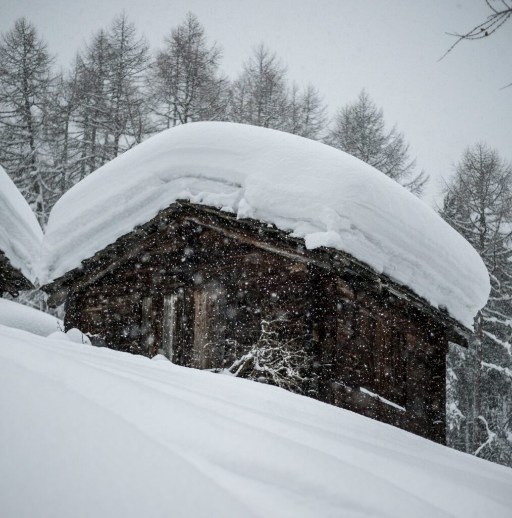
What Is Ground Snow Load?
Ground snow load (Pg) is a measure of the weight of snow that accumulates on the ground in a specific location, representing the maximum expected snow accumulation at that site. It serves as the baseline for calculating the roof snow load, which is critical for designing structures to withstand snow-related forces. Pg is derived from historical data collected at weather stations, reflecting typical snow accumulation patterns for the region.
For structural design, Pg can be obtained from resources such as the ASCE 7 Standard (Chapter 7, Figure 7.2.1) or the ASCE Hazards Tool. In areas marked as “CS” in ASCE 7, site-specific studies may be needed due to significant variations in snow accumulation. The ground snow load must be approved by the Authority Having Jurisdiction (AHJ), and additional research may be required, though some information can be found on the ATC website. Always check with your local building department to confirm the local ground snow load.
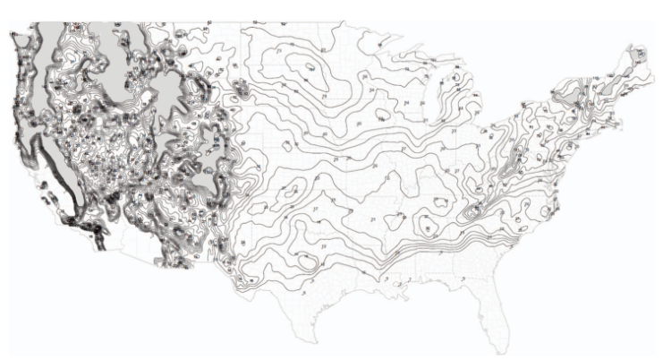
Ground Snow Load Data from ASCE 7-22 (Chapter 7, Figure 7.2.1)
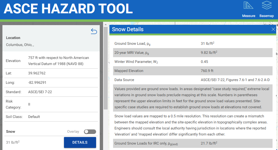
Ground Snow Load Data from ASCE Hazard Tool
What about Roof Snow Load?
Roof snow load is the amount of snow that a roof is expected to support, which is critical for designing safe and durable structures. While the ground snow load provides a baseline, it is not the actual load applied to the roof. The roof snow load can be calculated from the local ground snow load using the equations found in Chapter 7 of ASCE 7. This calculation is influenced by several factors, including the roof’s shape, slope, thermal conditions, and exposure to the elements. For some conditions, the Roof Snow Load may actually be lower than the Ground snow load in the area!
Roof snow loads are calculated in stages, starting with a general flat roof load. This is then adjusted based on the roof’s slope and the potential for snow drift that can accumulate from nearby structures.
Flat Roof Snow Load (Pf)
For flat roofs (slope ≤ 5°), such as those in patio enclosures or carports, the flat roof snow load is calculated using the following formula from ASCE 7, Formula 7.3-1:
Pf = 0.7 × Ce × Ct × Is × Pg
Where:
- Pf = Flat Roof Snow Load
- Ce = Exposure Factor: This accounts for the structure’s exposure to wind and its surroundings, affecting how snow is deposited on the roof.
- Ct = Thermal Factor: This factor considers the heat generated by the building, which affects how snow melts or accumulates depending on the temperature of the structure.
- Is = Importance Factor: This adjusts for the intended use of the building, with higher importance given to buildings that are essential or have a higher occupancy.
- Pg = Ground Snow Load
Sloped Roof Snow Load (Ps)
Sloped roofs are treated differently from flat roofs because snow behaves differently depending on the angle of the roof. On sloped roofs, snow can slide off more easily, reducing the load compared to a flat roof where snow may accumulate more heavily. Therefore, sloped roof snow loads are calculated using different methods to account for this difference in snow accumulation and movement.
For roofs with a slope ≥ 5°, the snow load is calculated differently than for flat roofs. Snow loads on sloped roofs are determined based on the horizontal projection of the roof, meaning the snow load on a sloped roof is generally less than or equal to that on a flat roof.
The sloped roof snow load (balanced) is calculated using Formula 7.4-1 of ASCE 7:
Ps = Pf × Cs
Where:
- Ps = Sloped Roof Snow Load
- Pf = Flat Roof Snow Load
- Cs = Roof Slope Factor: Found in Table 7.4-1 of ASCE 7.
General Comparison
When comparing ground snow load to roof snow load, here are some general observations to help you understand the key differences. Additional factors, such as wind, seismic forces, minimum code requirements, and site-specific conditions, all contribute to the final load condition used for design.
Determining the correct design loads is a complex process that requires expertise. It should be performed by a licensed design professional. To ensure proper calculations and obtain certified plans for permits, we recommend contacting us for assistance in determining the factored load calculations tailored to your specific conditions.
Using a 20 psf Ground Snow Load:
THE DESIGN LOADS PROVIDED ARE GENERAL EXAMPLES & MAY NOT BE USED FOR DESIGN, CERTIFICATION OR PERMITTING. ENGINEERING CALCULATIONS REQUIRE A VALID CERTIFICATION FOR USE
| Exposure Factor Category (Surface Roughness) | Resulting Exposure factor Ce (Partially Exposed) |
Structure Type Examples | Thermal Factor, Ct | Importance Factor, I (Patio: Risk II) |
ROOF SNOW LOAD Flat (< 5 degrees), PSF |
ROOF SNOW LOAD Sloped Roof (30°) Unobstructed Slippery Surface (FIG 7.4-1), PSF |
ROOF SNOW LOAD Sloped Roof (30°) All Other Surfaces, PSF |
| B | 1.0 | Pergola & Open Air Structures (Cold) | 1.2 | 1 | 16.8 | 13.1 | 16.8 |
| 1.0 | Continuously Heated Sunroom / Greenhouse (Warm) | 0.85 | 1 | 11.9 | 7.4 | 11.9 | |
| C | 1.0 | Pergola & Open Air Structures (Cold) | 1.2 | 1 | 16.8 | 13.1 | 16.8 |
| 1.0 | Continuously Heated Sunroom / Greenhouse (Warm) | 0.85 | 1 | 11.9 | 7.4 | 11.9 | |
| D | 0.9 | Pergola & Open Air Structures (Cold) | 1.2 | 1 | 15.1 | 11.8 | 15.1 |
| 0.9 | Continuously Heated Sunroom / Greenhouse (Warm) | 0.85 | 1 | 10.7 | 6.7 | 10.7 |
Other factors to consider
Snow Drift
One important factor to consider in snow load calculations is snow drift. This occurs when wind causes snow to accumulate against vertical surfaces, such as walls or taller roof sections, creating uneven loading on the structure. Snow drift can significantly increase the load on specific areas of the roof. However, calculating snow drift is a complex process that goes beyond basic load determination. For an accurate assessment tailored to your structure, we recommend contacting us for a professional analysis and certified calculations.
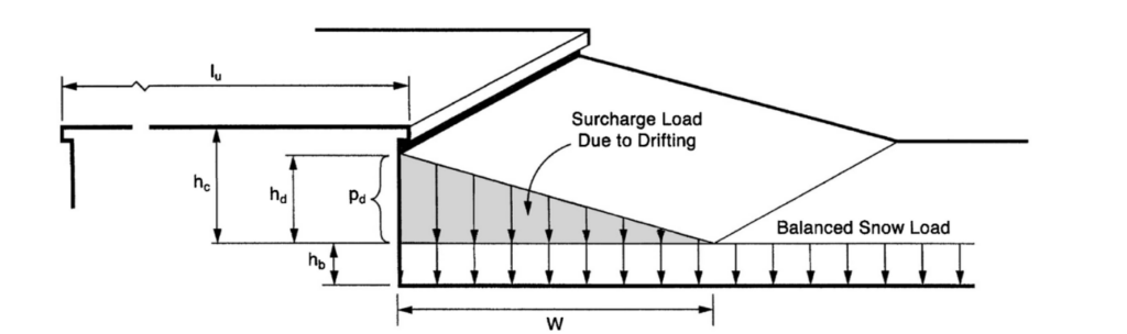
Configuration of snowdrifts on lower roofs, ASCE 7 Figure 7.7-2.
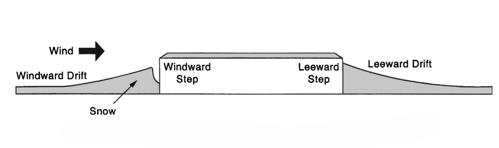
Drifts formed at windward and leeward steps, ASCE 7 Figure 7.7-1.
Snow Build Over
For open structures like trellises and pergolas, snow can accumulate and settle in unique ways, known as the snow build-over effect. This occurs when snow bridges between gaps in otherwise porous structures, such as the spaces between trellis slats, forming a continuous layer of snow. This bridging effect can lead to increased snow loads, as the snow may not fall off easily or evenly, creating unexpected pressures on the structure. For a simple explanation and practical guidance, check out our dedicated article. Click here to read more!
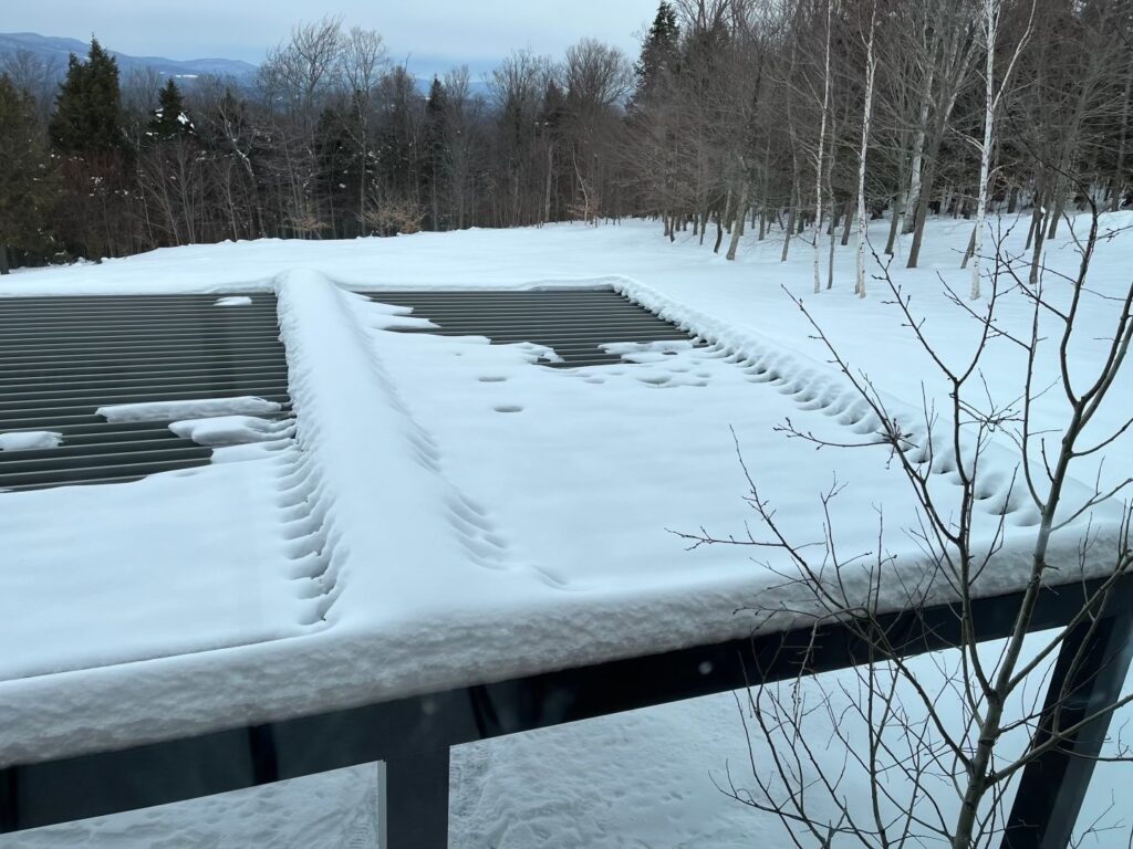
Exemple of Snow Buildup On Open Roof Areas.
Icing
Ice accumulation is another condition to keep in mind when evaluating structural loads. This occurs when snow melts and refreezes or when freezing rain builds up on surfaces, adding significant weight to the structure. The ASCE 7 Standard includes an icing chart and methodology for calculating this additional force. For a simple explanation and practical guidance, check out our dedicated article. Click here to read more!
Now that Ground and Roof Snow Load hold no secrets for you, we wish you the best of luck with your upcoming projects! If you have any questions about project design or need engineering assistance, simply click the button below to get in touch with us. Don’t forget to explore our other engineering articles for more valuable insights and tips!
Snow Load Calculation Tool
Use this external tool to calculate your snow load & snow drift on your project with your ASCE Hazard Tool Data
Use The Snow Load Estimation Tool
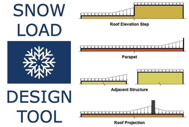
For more detailed information and guidance on handling your future design projects, check out our online design calculators, contact us for site-specific projects, or reach out to us with your inquiries.
Online Design Calculators
Site specific engineering request
Chat with an engineer
Tell us how can we improve this post?
Performance Limitations for Mechanical Equipment & TER Certifications
Summary of Building Code & Research Intent
The intent & provisions of the 2018 International Building Code (IBC), 2018 International Residential Code (IRC) & 2020 Florida Building/Residential Codes are to establish minimum
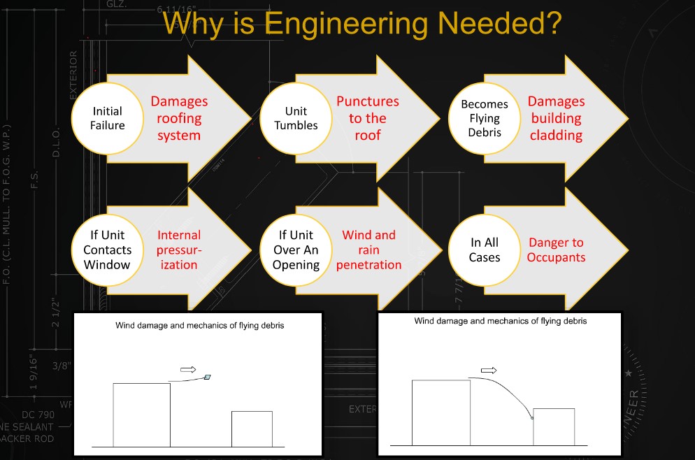
requirements to safeguard the public safety, health, and general welfare of occupants of new and existing buildings & structures.
From 2022 / 2020 FBC, 8th/7th Edition, Chapter 1 [A]101.3 Intent.
The purpose of this code is to establish the minimum requirements to provide a reasonable level of safety, public health and general welfare through structural strength, means of egress facilities, stability, sanitation, adequate light and ventilation, energy conservation, and safety to life and property from fire and other hazards attributed to the built environment and to provide a reasonable level of safety to fire fighters and emergency responders during emergency operations.
While not ideal, the safety & well-being of the public comes first as a code-minimum standard.
The building codes relate to the design of mechanical equipment, whether part of the building envelope or outside & not part of the building envelope.
* The safety & welfare of the public is compromised when a mechanical unit jeopardizes the integrity of the building envelope. This occurs when a rooftop unit is dislodged & an opening in the rooftop creates building envelope internal pressurization or a rooftop or ground-mounted unit disassembles during a wind event & creates flying debris which can jeopardize the integrity of surrounding buildings (see graphic).
The wind design of mechanical units follows Chapter 16 of the Florida or International Building Codes (2020/2018 linked respectively). Specific attention is drawn to loading on ‘other structures’, which is a separate design component of ASCE-7 (Chapter 29, ASCE 7-16). Section 29.4 relates to ground or roof-mounted unit wind design. Section 30.10 describes rooftop structures & equipment design for buildings & explains forces shall be considered to act inward & outward on the surface wall and in upward directions.
This design does not define deflection or permanent-set limits after a wind event but implies integrity must be maintained of the unit as a whole.
Additionally, the 2020 Florida Building Code defines in Chapter 28, Mechanical Systems – Mechanical Code Section 301.15 Wind resistance. Mechanical Equipment, appliances & supports that are exposed to wind shall be designed & installed to resist the wind pressures determined in accordance with the Florida Building Code, Building (with exceptions).
Additional publications which further define the minimum standards of design include:
- AHRI 1310p, which states Section 1.1.1 Intent. This standard is intended to provide guidance regarding the minimum requirements of exposed equipment cabinetry to safeguard surrounding elements from windborne debris damage through structural strength to resist wind forces that cause overturning, sliding or separation of unit components.
- See also Florida House Bill 535 663, 704 (FS 5523.844) Senate Bill SB 1040 for additional certification requirements & limitations as they pertain to requirements of design in Florida.
- See also ASHRAE Journal, Vol 48, No 3. P 36-43. Reinhold, T.A. (2006) Wind Loads & Anchorage Requirements for Rooftop Equipment
- See also IBHS “Wind Loads on Small Roof-Mounted Air Conditioning Units”, Morrison, Murray J., Ph.D. (2013) (Insurance Institute for Business & Home Safety)
- See also Journal of Wind & Engineering, “Wind Loads Rooftop Equipment Mounted on A Flat Roof” 8(1), 23-41, Erwin, J.W., Chowdhury, A.G. & Bitsuamlak, G. (2011)
- See also “Wind Loads on Roof-Mounted Cube (BLWT-SS47-2007), London, ON, Canada, The Boundary Layer Wind Tunnel Laboratory, Kopp, G.A. & Traczuk, G. (2007).
The Code is to be a minimum requirement that is flexible and affordable. It isn’t intended to inhibit competition and it should promote innovation and the use of new technology. The primary goal is the minimum standards for public health and safety. The secondary goal is for the protection of property.
What Engineers Certify With Performance Evaluations
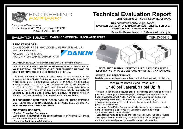
Performance Evaluations are a generic code-minimum requirement for installing mechanical units (air compressors, package units, generators, etc). They establish a maximum static-force pressure rating (typically in ASD, allowable stress design as noted on the evaluations) that the cabinet in question can theoretically withstand at the time of installation per the above-referenced codes & standards. This evaluation is based on a combination of recognized testing & rational analysis for the overall diaphragm, each panel component, and unit tie-down.
The maximum pressure rating establishes a performance baseline under which the unit can adequately resist the imposed static wind loading without experiencing failure of the unit cabinetry or tie-down system, as defined in the evaluation.
If the unit is designated for an essential facility, it must also pass large missile impact testing & certification. Missile Impact is a test-only phenomenon that is governed by ASTM E1886 & ASTM E1996.
Per FBC 453.24.5:
Electrical & standby emergency power systems… When generators are installed, the facility housing the generator, permanent or portable, shall be an enclosed area designed to protect the generators from wind & missile impact. Generators hardened by the manufacturer to withstand the area’s design wind & missile impact criteria shall be exempt from the enclosed area criteria requirement.
In the Florida Building Code 2020 section 1626.1.d – an exemption states that HVAC equipment does not require impact protection for “standard facilities.
Refer to our article on missile impact requirements for mechanical equipment in essential facilities by clicking here.
This exemption means that generators for residential units do not have to go through testing & impact certification & are subject to damage & dislodgement when impacted with design-force impact debris. Our Technical Evaluation Reports make it clear that certification of the unit does not apply to systems subjected to impact forces. Consequently, the unit’s operation is not guaranteed after a design event.
What Isn’t Covered Within Performance Evaluations
In addition to static load, non-impact limitations of non-essential facilities & the certification for missile & wind forces within static facilities, it is critical to understand that performance evaluations do not comprise a certification of any
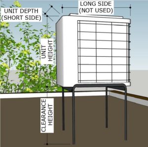
system or unit at a site-specific location.
A Design Professional (such as a licensed professional engineer or registered architect certified to practice within the state of the project location) must determine the site-specific conditions to interpret the design wind velocity and resulting wind pressure(s) acting on the unit in question. Factors such as the installing height from grade, geographic exposure, flat/hilly terrain (escarpment), the geometry of the unit, unit location relative to the roof layout, and vortex-contributing factors, among others, all contribute to the wind velocity-to-pressure conversion. Using a sealed TER without a design professional’s site-specific review is a violation of the code and does not constitute acceptable engineering for permit or installation.
Engineering Express publishes a rooftop equipment wind velocity to pressure calculator to demonstrate these variables for design professional estimation. We also publish a Forces Guideline Page to assist in adapting the results to a site-specific condition as a public service.
Important Limitations of Use & Code Compliance
In addition to specifying the installation conditions for wind pressure certification, Technical Evaluation Reports specify that the manufacturer, installing contractor, and end-user collectively have responsibilities for maintaining performance as well. These limitations may or may not be directly incorporated in the evaluation report or contract documents but are within communication with the client and indirectly referenced herein via the URL & QR codes found on reports. These include:
Survivability:
Evaluation reports are valid for a newly installed unit and do not include certification of the product beyond a design event if impacted. Inspections shall be implemented during annual equipment maintenance or after a named storm. All fasteners and cabinet components are to be verified, and all damaged, loose, corroded, and/or broken fasteners and cabinet components shall be replaced to ensure structural integrity against hurricane wind forces. Contact this office for any reevaluation needs as designated by the Authority Having Jurisdiction.
Durability:
Components or component assemblies shall not deteriorate, crack, fail, or lose functionality due to galvanic corrosion or weathering. All supporting components that are permanently installed shall be protected against corrosion, contamination, and other such damage at all times. Each component or assembly shall be supported and oriented in its intended installation position. All exposed plastic components shall be certified to resist sunlight exposure as specified by ASTM B117 or ASTM G155 in Broward or Miami-Dade counties.
Extent of Certification:
Certifications pertain to the structural integrity of the unit components listed within the evaluation, subject to the limitations and criteria stated therein. Operability and water infiltration are outside the bounds of this certification. No other certifications are intended. This evaluation alone does not offer any evaluation for large missile impact debris or cyclic wind requirements unless specifically stated within the evaluation.
UNDER NO CIRCUMSTANCE DO ANY OF OUR PERFORMANCE EVALUATIONS GUARANTEE, IMPLY, OR STATE THAT THE PERFORMANCE OF THE UNIT IS MAINTAINED DURING OR AFTER A DESIGN EVENT.
* Items in bold-italic represent the opinions of this firm, and while it is of the opinion of the firm that they are adequately researched & documented, they do not describe facts or necessarily refer to specific code compliance.
Tell us how can we improve this post?
Sunroom Terminology
The following is a summary of sunroom-related terms provided courtesy of the National Sunroom Association.
Click Here for the official publication provided by the NSA, reprinted here for informational purposes.
The terminology information encompasses many common terms used in the sunroom industry. You will note
that some terms are cross-referenced to a “primary” term. The “primary” term is the one that would be used
most often in sunroom publications.
Concerning the term and definitions contained in this Sunroom Data Sheet, please note the following:
• This Sunroom Data Sheet is not to be construed as a standard-type document, and therefore the
terms and definitions contained therein do not imply or suggest a given use to particular
manufacturer.
• This Sunroom Data Sheet includes a compilation of commonly used terms, and may not be
considered complete from an industry viewpoint.
• The terms and definitions are not universal. Variations within the industry may exist with regard to
precise meaning.
2021, rev. 4/1/21 – NSA
Note: This document is reviewed periodically and may be updated. Visit www.nationalsunroom.org for the latest version.
Awning Window: A hinged window that opens horizontally.
Batten: A two-piece assembly that facilitates the attachment of two roof components.
Casement Window: A hinged window that opens to the left or the right via a cranking mechanism.
Chase Way: An opening in an extrusion allowing wires to be run internal to the wall system.
Cricket: A roof structure that is designed to divert water around an obstacle or low point to ensure water is
properly evacuated, and is normally the same pitch as the rest of the roof.
Double Hung Window: An operable window with two sashes where both the top and bottom sash will
operate to allow for additional ventilation.
Electrical Box: Plastic or metal box that can be used to make electrical connections, house outlets, or
switches, and should be listed and CPSC compliant.
Engineered Lumber: See Laminated Verneer Lumber.
EPS: A type of foam plastic, known as expanded polystyrene, used for its insulative properties in sunrooms.
Fascia: A decorative component used to cover and seal the end of a roof panel, to reduce opportunity for water
infiltration and aesthetically change the look of the end of a roof system.
Flashing: Sheet of thin, impervious, exposed or embedded material used to prevent water penetration into a
building and to direct the flow of moisture in walls.
Footing: Concrete, block, or aggregate piles set below the frost line to support the foundation and prevent
heaving or settling of a structure; the sizing of these must be properly engineered to support the room and
support structure being built.
Frame: Exterior assembly that contains the window sashes and screens.
French Door: A swing door that has two panels, both of which open from the middle and can open either to
the inside or outside of the home.
Frost Line: The depth of frost penetration in solid ground, or the depth at which the earth will freeze and swell,
dependent on the geographic location.
Gable Roof: A room that peaks in the middle, as looking at the existing structure, that slopes down to the
outside walls on both sides.
Garden Patio Door: A swing door with two panels, only one of which opens, that can open from the outside
framing or center mullion and can swing inside or outside of the home.
Glazing: Rubber or silicone bedding that seals the glass to the window sash.
Glazing Bead: Removable component of a window sash that is snapped in to hold an insulated glazing unit in
place.
Gutter: A type of side fascia that is designed to capture water running off of the roof, channel it to a specific
low point, and allow it to evacuate.
Header: Top horizontal structural component of a window, door, or wall section.
Hip Roof: A roof that has four inclined sides.
I-Beam: A structural roof mullion that facilitates the attachment of two roof components.
Jamb: Vertical window or door frame component that provides vertical structure to the unit.
J-Channel: Vinyl or aluminum component that is used to enclose the cut end of siding to provide a clean finish.
Joist: A horizontal structural member used in framing to span an open space, often between beams that
subsequently transfer loads to vertical members.
Keeper: Fixed component of a window lock that accepts the lock cam.
Knee Wall: A wall or window less than three feet in height used as a base wall in a sunroom application,
typically either glass picture windows or foam core panels with aluminum or vinyl skins.
Lag Screw: A mechanical fastener used to connect load bearing lumber or other materials.
Laminated Verneer Lumber (LVL): Lumber with specific engineered properties, used for the building of
sunrooms and decks.
Ledger Board: A horizontal lumber beam attached to an existing wall and used to tie in construction elements
such as porch roofs and decks.
Monoslope Roof: See Shed Roof
Mullion: Vertical or horizontal component used to join two units together such as window to window, window
to door, or unit to framing, within an opening or sunroom wall system.
Peak: The highest point of the room structure, which can be internal within the room or external where the top
of the roof will tie in to the home.
Picture Window: A non-operable window used in a replacement or sunroom application.
Pier: A vertical load bearing member of a deck or support structure for a room.
Pitch: Slope of a roof panel, typically in inches of vertical increase per 12 inches of horizontal travel.
Post: Vertical component used to carry loads on a structure.
Raceway: A cavity within an extrusion that is used to house electrical wires internal to a wall system. [Note:
Unless electrical connections are being made in this cavity, it is not typically required to be UL listed. If products
do not carry a UL listing, all electrical connections must be made within a labeled box to be compliant with codes.]
Ridge Cap: External assembly attached to a roof to allow venting from within the space.
Rim Joist: A joist attached perpendicular to other joists, providing lateral support for the ends of
the joists while capping off the end of a floor or deck system.
Roof Panel: Multi-ply panel used to cover the top of the room and bear any environmental loads (either snow
or wind) associated with sealing the room.
Sash: Operable portions of horizontal sliding, vertical sliding, and hinged windows.
Shed Roof: Single slope roof that slopes away from the existing structure.
Side Lite: Unit placed next to a door to give the illusion of another door lite panel, used to maintain a door
aesthetic while utilizing a configuration in lieu of a larger door.
Sill: The bottom component of a window, door, or wall section, meant to tie directly to an opening or framing
and facilitate water evacuation from a system.
Sill Plate: Bottom horizontal member of a wall or building to which vertical supports are attached.
Single Hung Window: An operable window that has two sashes where only the bottom sash will operate.
Skylight: A fixed or operable window installed in the roof of a structure to allow for additional ventilation or
light entry into a space.
Slider Window: An operable window that has two or three sashes that slide horizontally for ventilation.
Sliding Glass Door: A two to four sash door with a combination of fixed and operating lites that slide to allow
for egress and ventilation.
Studio Roof: See Shed Roof
Swing Door: A single or dual panel door hinged on one side and designed to swing in or out.
Tie-In: Mechanical fastening and sealing of the room and roof to the existing structure.
Transom: Unit that is placed over top of a standard wall unit to allow for increase wall height.
Trapezoidal Panel: Angular window with 4 sides, typically used directly under the roof on the pitched wall
of the room.
Wing Panel: Trapezoidal panel located between the windows and the roof on the pitched side.
Wool Pile: Material commonly inserted in window sashes and frame to seal two moving components, placed
to reduce the amount of air or water infiltration through an opening while still allowing the components to
operate
Tell us how can we improve this post?
Door and Hardware Online Glossary
Thanks to our partners at ASSA ABLOY, we’re happy to pass along this helpful glossary of industry lingo. Learn all about the many terms used in the door and hardware industry
Click here to visit the ASSA ABLOY Glossary
Tell us how can we improve this post?
ASCE 7 WIND EXPOSURE CATEGORIES AND HOW EXPOSURE ‘D’ WORKS
Wind Exposure Category Overview
ASCE-7 is the governing referenced standard for design loads on buildings & other structures for building codes throughout the US. ASCE 7 (26.7 of ASCE 7-16) describes the process to which wind speed is converted into wind pressure to design such structures. The formula is based on many variables. One of which is called ‘Exposure Category’ and reflects the characteristics of ground surface irregularities at a site which the building or structure is to be constructed. The rougher the surface, the lower the multiplier that converts wind speed to pressure.
Click here to learn more about the conversion of wind speed to pressure.
Watch as company founder Frank Bennardo PE explains the uses of Exposure Categories
& where they apply, including Exposure D.
About Exposure D & ASCE 7
Exposure ‘D’ is the largest multiplier when converting wind velocity to wind pressure, representing coastal areas and the ‘smoothness’ of water relative to wind.
Non-coastal areas have Exposure categories B and C with greater roughness coefficients.
The exact dimension of where Exposure D lies relative to the coast is a moving target and based on the height of the building in question.
Below is a how-to checklist in determining Exposure D. Be sure to see our graphic below for an easier visual representation. The example & illustration have been verified for use with ASCE 7-22/16 as well.
Exposure D Calculation Checklist:
1. Confirm surface roughness distance and the initiation point of Exposure D:
The Initiation Point (Ip) of Exposure D occurs at the point on land where “Surface Roughness D” prevails in the upwind direction for a distance of 5000 feet minimum
(Think: the ‘runway’ for wind approaching the structure shall be at least a mile – 5,280ft to create an exposure D area or start/insertion point).
INITIATION POINT (Ip) = SURFACE ROUGHNESS > 5000FT
2. Determine the distance of the structure from the initiation point (Sdist)
3. Confirm primary Exposure D region:
The primary Exposure D condition occurs (for all structures) from the Exposure D Initiation Point at the directly exposed coastline area (that mark that was at the end of the runway above), running inland for a distance of 600 feet (Dprimary = 600 FT)
(Think: Any structure 600 ft from what we have determined creates Exposure D).
AND IF (Sdist) < (Dprimary) THEN EXPOSURE D APPLIES.
4. Confirm building-specific Exposure D region:
A secondary Exposure D condition may occur based on the structure itself.
To determine the building-specific Exposure D region, multiply the Mean Roof Height (MRH) of the structure by 20
(Dsecondary=MRH*20).
Compare Dsecondary to the Sdist.
(Think: D can be greater than 600ft from this insertion point if the structure’s distance is less than or equal to the height of the structure * 20).
IF (Sdist) < (Dsecondary) THEN EXPOSURE D APPLIES
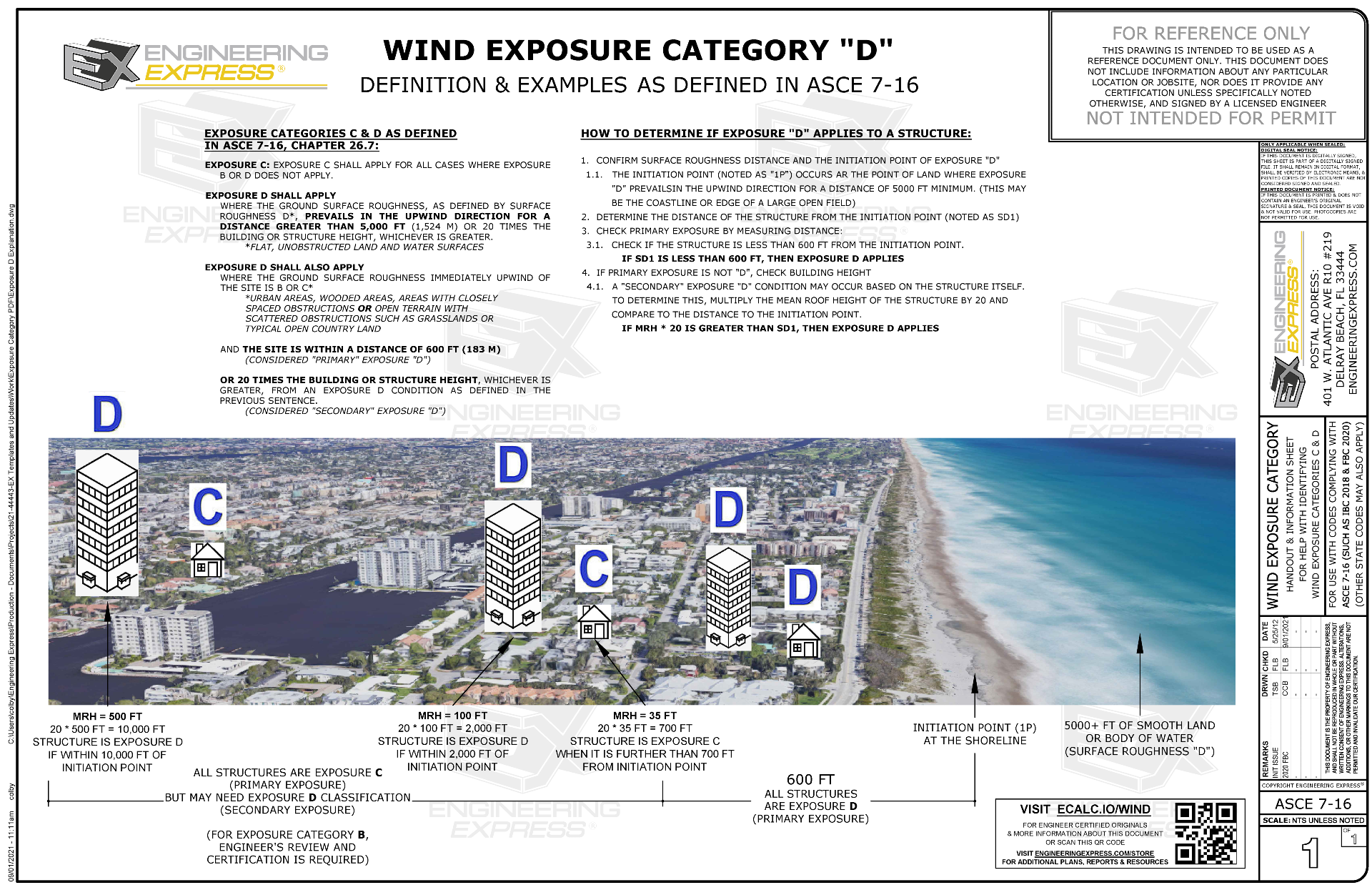
Click for larger image of visual explanation of Exposure D
Visual Example of Exposure D Per ASCE 7:

Visual Representation Of Exposure Roughness from ASCE 7 Commentary:
From C26.7-2

Something Else To Consider
Something to note, ASCE 7 has expanded on the application of exposure categories by clarifying a directional requirement for (8) sectors of wind directions.
An Exposure of one condition could exist in one sector but not another. This was in previous ASCE standards but was expanded upon in the commentary.
From ASCE 7 26.7.1 (exists in earlier ASCE 7 codes): Wind Directions and Sectors.
For each selected wind direction at which the wind loads are to be determined, the exposure of the building or structure shall be determined for the two upwind sectors extending 45° on either side of the selected wind direction. The exposure in these two sectors shall be determined in accordance with Sections 26.7.2 and 26.7.3, and the exposure that would result in the highest wind loads shall be used to represent the winds from that direction.
From the ASCE 7 Commentary, this illustration has been expanded:

We recommend consulting with the ASCE 7 design manual for more information before use in designing a project for wind & using directional exposures with caution. The worst case is always recommended.
Other Exposure Categories:
(With excerpts from ASCE 7 Commentary to help explain):
Exposure Category A
Exposure A was deleted. Previously, Exposure A was intended for heavily built-up city centers with tall buildings. However, the committee has concluded that in areas in close proximity to tall buildings the variability of the wind is too great, because of local channeling and wake buffeting effects, to allow a special category A to be defined. For projects where schedule and cost permit, in heavily built-up city centers, Method 3 is recommended because this will enable local channeling and wake-buffeting effects to be properly accounted for. For all other projects, Exposure B can be used.
Exposure Category B
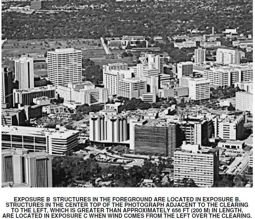
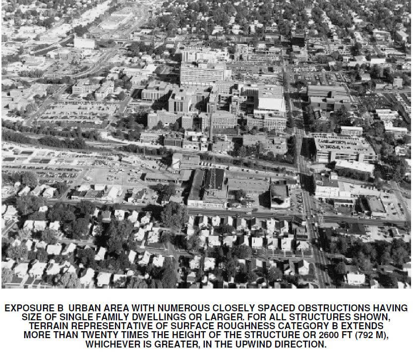
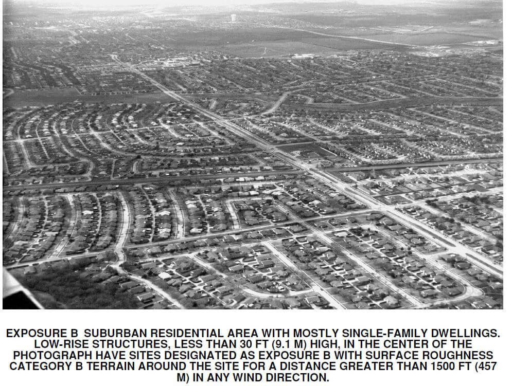
Exposure Category C
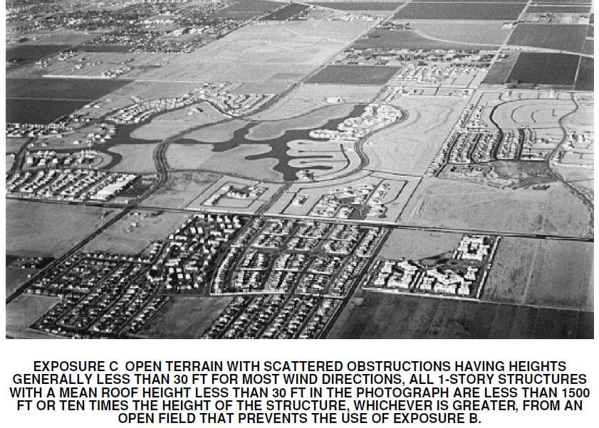
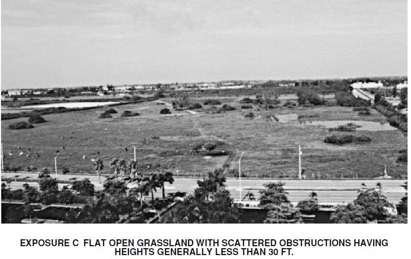
Frequently Asked Questions about Wind Exposure Categories and Exposure ‘D’
Q: What is wind exposure categories?
A: The Wind Exposure Categories were developed by ASCE in order to provide guidance on the design of structures for different wind environments. The categories range from B-D, with D being the most severe and B being the least severe.
Q: What is Exposure D?
A: Exposure D is a category of wind exposure that is used for structures located in coastal or open terrain as described in this article.
Q: What is the difference between Exposure C and Exposure D?
A: The main difference between Exposure C and Exposure D is that Exposure C is used for structures located in urban or built-up areas, while Exposure D is used for structures located in coastal or open terrain.
Q: How is Exposure D determined?
A: Exposure D is determined by the distance of the structure from the coastline or large are of open land per formulas described in this article.
Q: What is the ASCE 7 Standard?
A: The ASCE 7 Standard is a set of guidelines that are used in the design of structures for different loading environments.
Q: What is the difference between Exposure C and Exposure D?
A: The main difference between Exposure C and Exposure D is that Exposure C is used for structures located in urban or built-up areas, while Exposure D is used for structures located in coastal or open terrain, as described in this article.
Tell us how can we improve this post?
FAQ Search our AC model Database
Click Here to access our model database tool. You can filter by your AC brand, model, and number to find the TER report you need to purchase for permit.
Tell us how can we improve this post?
I see values for F1 and F2 on Evaluation Reports. What are they?
F1 and F2 are the limiting performance capacities of the forces in the parallel and perpendicular directions of a building component. Which one is which direction appears in a guide in each TER or corresponding test reports.
There’s also an interaction between the 2 forces that cannot be exceeded which is also explained on the reports. it’s either a linear or parabolic interaction that requires the unity of both forces to be less than 1.0. This information is to be reviewed with and by a design professional for each project.
Tell us how can we improve this post?
Learn About Rooftop & Ground Wind Forces for Mechanical Units
Want to learn how to design AC units on stands or curbs for wind design?
Are you looking for tools to help in in design?
Visit our FORCES page to learn more.
Tell us how can we improve this post?
About Door Product Pressure Ratings and Water Infiltration
Why Door & Window Wind Pressure Ratings Are Not What They Appear
Your installation may NOT be rated to the pressure listed on the cover page – Here’s why.
You’ll frequently see that a building product (such as a door, window, etc.) is ‘approved’ up to a certain wind pressure.
Many times, that approved pressure is for an ideal condition, and many other factors may exist that LOWER the rated design pressure.
This article explores 4 ways the rated pressure can be reduced from it’s maximum design rating.
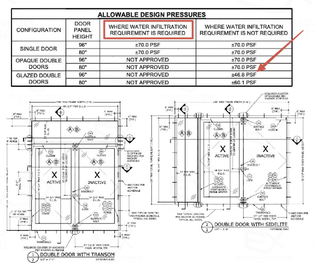
See this product approval online
Reason #1: Comparative Analysis Size
You’ll notice at the arrow in the image above that the approved pressure for the glazed double doors decreases as the door panel height increases.
It’s important to find the size opening you need within the evaluation reports to determine if your size is approved, and to what pressure.
The example above illustrates a considerable drop-off in pressures as the door height increases, but it’s ‘rated’ for the highest design pressure.
Reason #2: Water Infiltration Limitations
The ‘rated’ product pressures may not take the water testing & infiltration conditions into consideration.
You can see from the red box in the image above that water infiltration requirements limit the product to only some approved instances.
A deeper search into the evaluation will likely reveal limitations of performance if water infiltration is required.
Water Infiltration Explained
In Florida, the 2023 Florida Building Code section 1709.5.1 exempts water infiltration testing if:
1. Door assemblies installed in nonhabitable areas where the door assembly and area are designed to accept water infiltration need not be tested for water infiltration.
2. Door assemblies installed where the overhang (OH) ratio is equal to or more than 1 need not be tested for water infiltration. The overhang ratio shall be calculated by the following equation:
-
-
OH ratio = OH Length/OH Height
where:
-
OH length = The horizontal measure of how far an overhang over a door projects out from door surface.
-
OH height = The vertical measure of the distance from the door sill to the bottom of the overhang over a door.
-
NOTE: Pass-through windows for serving from a single-family kitchen, where protected by a roof overhang of 5 feet (1.5 m) or more shall be exempted from the requirements of the water infiltration test.
This also appears in FBC 2023 HVHZ section 2411.3.2.1
Once water resistance is required, the structural positive pressure may be lower.
On doors there is usually a variation of thresholds with different approved design pressure ratings.
The 2021 IBC references testing of exterior windows and doors in their section 1709.5 which differs from the Florida Building Code but still lists test requirements.
Reason #3: Component Substitution
Image credit Beacon Commercial Door & Lock
Switch a lock, hinge, frame, or glass type? – The pressure is only approved to the lowest rated product.
Changing the 3-point lock on a door to a panic device similar to the Von Duprin Exit Device below? The rated door pressure is bound to change.
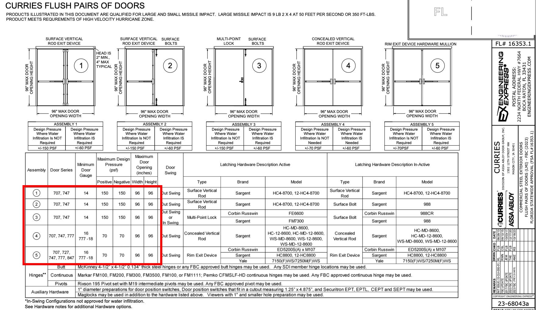
Click image to enlarge or click here to see this approval online
Many approvals list some substitutions, but it’s impossible to have every combination of every part for every door.
That’s why engineers like Engineering Express are skilled in creating product approvals and rating component substitutions for your project.
Contact us to discuss your custom engineering design need.
Reason #4 – Using Allowable vs. Ultimate Design Pressures
We published this article to explain the difference between using ASD (allowable Stress Design) or LRFD (Factored, or Ultimate) pressures.
Put simply:
– The ASD ‘reduces’ the’ breaking point’ of a component so a lower value is used.
– The LRFD ‘increases’ the load you are using before comparing to the actual breaking point.
Many approvals state ASD pressures, reducing the allowable load a building product can withstand, but more and more are now using LRFD.
It’s imperative that you calculate AND use the proper pressure format to compare like-to-like components.

Click the image to read the ASD vs LRFD Article
Use Our Wind Pressure Tool
Request A Component Evaluation Quote
Tell us how can we improve this post?
What are The Span Limitations of Large Missile Impact Doors – Windows – Shutters?
Size Limitations For Impact Rated Products
A Frequent question is what are the span, height, pressure, and installation limitations for large & small missile impact products.
The following takes into consideration the Florida Building Code 8th Edition (2023) limitations for designing & installing operable and non-operable windows/glass doors & impact protection devices.
This also applies to wind-borne debris regions throughout the US where ultimate design wind speeds are >=140mph, wind is >=130mph and within 1 mile of the coastline or exposed to open water, the IBHS FORTIFIED program, & as defined by the International Building Code.

For Operable Windows & Glass Doors
Inside the HVHZ (Broward & Dade Counties)
For the 8th Edition of the Florida Building Code (previous codes are similar), Chapter 2411.3.2.4.i is summarized as:
- For Windows and Doors other than bifold or sliding glass doors, the tested frame area (Frame width x Frame Height) shall not be exceeded the frame area of the tested approved unit.
- For sliding or bifold glass doors, the tested panel area (Panel width x Panel height) shall not exceed the panel area of the tested approved unit. If the door stiles or interlocks do not meet FBC 1616.3.1(6), the maximum allowed unit’s frame area shall be limited to 1.5X the tested frame area.
- Frame sizes shall vary from the tested approved unit only in width, height, or load requirements and shall not exceed 100% deflection, stress, concentrated load, water infiltration, or cyclic pressure of the tested approved unit per TAS 201, 202, 203 (see them here or see all TAS Protocols here – click left side, no sign-in required).
TAS 203 section 5.1 specifically states: “All Parts of the specimen shall be full size”.
TAS 202 Section 5.4 states “Specimens sucessfully tested shall qualify assemblies of a smaller size & of the same type and construction, provided the anchorage of the product remains unchanged”.
- Takeaway: In all cases, the tested frame height (structurally loaded direction) & pressure shall not be exceeded.
Please refer to the full code text of 2411.3 for more information as the above is a summary.
Outside the HVHZ ( Other than Broward & Dade Counties)
The code is written essentially the same for non HVHZ areas of Florida.
See section 1709.5.1(3) for the 2023 FBC text.
For Non-Operable Windows
Inside the HVHZ (Dade & Broward Counties)
For the 8th Edition of the Florida Building Code (and numerous previous codes), Chapter 2411.3.2.4.ii is summarized as:
- The frame area of the alternate size unit shall not exceed the frame area of the tested approved unit.
- Shall vary from the tested approved unit only in width, height or load requirements.
- The maximum uniform load distribution (ULD) of any side shall be equal to the uniform load carried by the side divided by the length of the side.
- The ULD of any member shall not exceed the ULD of the corresponding member of the tested approved unit & shall be calculated in accordance with standard engineering analysis.
- Shall not exceed the air and water infiltration resistance of the tested approved unit, or cyclic pressure of the tested approved unit when tested per TAS 201 and 203
- (see them here or see all TAS Protocols here – click left side, no sign-in required).
Please refer to the full code text of 2411.3 for more information as this is a summary.
Outside the HVHZ (Other Than Dade & Broward Counties)
The code is written essentially the same for non HVHZ areas of Florida.
See section 1709.5.1(3) for the 2023 FBC text.
For Large Missile Impact Protection & Similar Standards
Large missile impact protection systems, such as storm panels, accordion, roll-up, and fabric systems, all follow the same guiding principles.
Each have to pass a battery of impact & cyclical tests to ensure they remain intact after a category 5 storm.
https://www.youtube.com/watch?v=zorjGkHXK6U

Watch the engaging video of how storm panels go from coil to store shelves. The photo above is a large missile impact test hit (9lb 2 X 4 at 50ft/second).
![]()
A service provided by Engineering Express®
Get FORTIFIED Certified
This topic also applies to the IBHS FORTIFIED program.
Learn more about how to attract more insurance companies & earn discounts on insurances for following the FORTIFIED process.
Inside the HVHZ (Dade & Broward Counties)
Florida Building Code Section 1626 covers HVHZ Impact Tests For Wind-Borne Debris.
Miami Dade publishes guidelines that relate to the limitations of use for impact-protection products, windows, and doors. You can find those specifications here. Miami-Dade relies on numerous standards including the Florida Building Code & related referenced standards to adopt these criteria.
The Florida Storm Shelter Code ICC-500 is another referenced standard governing the limitation of use. Section 802.1 Test Assembly lists the following limitations.
All parts of the test specimen shall be full size, using the same materials, details, methods of construction and methods of attachment as proposed for actual use. Impact-protective systems shall be impact tested and cyclic pressure tested where applicable, at the maximum and minimum size listed for use. Static pressure testing shall be conducted on the maximum size listed for use. Operable door assemblies and window assemblies shall be tested for the conditions of swing and latching including inward or outward swing separately as specified for use of the product. Impact-protective systems shall be static pressure tested in both directions unless a clear worst-case direction is determined by the test laboratory.
Outside the HVHZ (Other Than Dade & Broward Counties)
Outside the HVHZ, ASTM E-1886 and E-1996 govern. Those codes frequently reference maximum frame sizes and spans for testing, water, and air infiltration.
For example, from ASTM E-1996 as referenced in the 2023FBC as a required standard for impact protection, Section A2.11 states:
ASTM E-1996 Panel Systems Section A2.11.1
Any modification to mounting hole size, shape, or location shall require the testing of one additional specimen, provided the diameter of the shape or both, of the hole are not increased or altered.
A2.11.2 Any substitution of a larger diameter or increased area mounting holes shall not be allowed.
ICC 500 is also a non-HVHZ criterion, as outlined above.
In Summary
Designing for large missile impact protection is unlike typical static load designs.
The main difference with designing for impact is how the product behaves after it gets struck by missiles – making the calculation nearly impossible to perform without testing.
After a tested product is impacted several times, it is then cycled thousands of times to levels above the design limits. The behaviour of the product cannot be estimated, rationally analyzed, or compared to other spans or pressures due to this degree of unknown.
This is why the test results are so important in developing impact-resistant systems. They simulate storms lasting hours, with multiple missile hits, and heavy rain infiltration.
Engineering Express would be glad to discuss your product or site-specific need. Start a quote request or chat with us to explore more.
Tell us how can we improve this post?
Requirements of Substituting Glass Panels In Insulating Glass Systems
ASTM 1996-17 Regarding Glass Substitution
Section A1.8 states: “A1.8.1.1 The impact resisting lite (monolithic or laminated) of an insulating glass unit shall be composed of the same glass type and treatment with equal thickness or thicknesses of glass, and thicker or equal interlayer of the same manufacturer and type as originally tested and approved.
Section A1.8 states: “A1.8.1.5 Glazing systems typically have a stationary glazing stop that is a permanent part of the frame or sash, or a removable glazing stop (also referred to as a glazing bead), or both. If a removable stop is used, a system can be tested with this stop removed, if it considered to be non-structural and unnecessary to pass the required test.”
Section A1.8 states: “A1.8.2 Systems Tested with a Removable Glazing Stop or Bead in Place.
Section A1.8 states: “A1.8.2.1 Any substitution to an insulating glass unit from a single glazing (monolithic or laminated glass) shall require the testing of one additional specimen provided the system meets all the preconditions in A1.8.1.
Note: This is assumed no additional testing is performed. ASTM provisions permit one additional sample can be tested to substitute spacers or glass. Contact Engineering Express to further discuss how we can develop a test protocol for your glazing system or provide a review & approval of glass or spacing substitution.
See also ASTM requirements for glass spacers
Tell us how can we improve this post?
Requirements of Substituting Insulated Glass Spacers in Glazed Products
ASTM 1996-17 Regarding Insulated Glass Spacers.
This 2017 standard added section A1.9.2 stating tested air spacers making up the insulated laminated unit can be substituted with other spacers.
“A1.9.2 If the conditions in A1.8.1.3 are met, a change in spacer type, shape, or dimension is allowed automatically.”
Section A1.8 states: “A1.8.1.3 Substitutions for insulating glass shall only be made for systems with the impact resistant glazing structurally adhered to the frame or sash glazing leg or bed in the same manner and position as originally tested and approved.”
Section A1.8 states: “A1.8.1.5 Glazing systems typically have a stationary glazing stop that is a permanent part of the frame or sash, or a removable glazing stop (also referred to as a glazing bead), or both. If a removable stop is used, a system can be tested with this stop removed, if it considered to be non-structural and unnecessary to pass the required test.”
***Structurally adhered or structurally glazed is a term used when no glass stops or glazing beads aided in the test. The only way to test is with stops off where the only element holding that glass in place is the sealant. ***
Note: This is assumed no additional testing is performed. ASTM provisions permit one additional sample can be tested to substitute spacers or glass. Contact Engineering Express to further discuss how we can develop a test protocol for your glazing system or provide a review & approval of glass or spacing substitution.
See also ASTM requirements of substituting glass on insulated panels
Tell us how can we improve this post?
Loss of Capacity Due To Welded Aluminum In Railings – Signs – Structures
Welded Aluminum Railings: Structural Risks, Code Requirements, and Design Considerations
Welded aluminum railings are commonly used in residential, commercial, and outdoor applications due to their durability, corrosion resistance, and clean architectural appearance. However, from an engineering standpoint, welding aluminum—especially heat-treated alloys such as 6061-T6 or 6063-T6—introduces critical structural considerations that must be properly addressed to ensure compliance with U.S. building codes and life-safety requirements.
Railings are classified as life-safety elements, particularly when installed at elevations greater than 30 inches above grade. As such, their design is governed not only by material properties but also by strict load requirements and connection performance criteria.
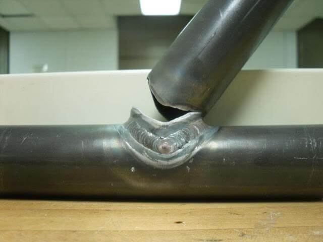
Structural Behavior and Code Requirements
Railing posts behave primarily as cantilevered members, with loads applied at the top rail generating bending moments that are resisted at the base connection. As a result, the maximum bending stress occurs at the base of the post, making this region critical for design. Building codes such as the International Building Code (IBC) require guardrails to resist a 200 lb (0.89 kN) concentrated load applied at the top rail (IBC 2021, Section 1607.8.1). Because this load produces peak stresses at the base, any weld located in this region directly reduces the effective load-carrying capacity of the system and must be carefully evaluated in design.
For example, a railing is classified as a life-saving fall guard for any elevation above 31 inches above grade. The aluminum alloys normally used (such as 6061-T6) get their strength from a heat-treatment process. Welding weakens the heat-treated aluminum in the vicinity of the weld, called the heat-affected zone (HAZ), reducing the strength by approximately 40 percent.

Effect of Welding (Heat-Affected Zone – HAZ)
Welding creates a heat-affected zone (HAZ) where the aluminum loses part of its mechanical strength due to thermal exposure.
-
6061-T6 typically degrades to approximately T4-level properties in the HAZ -
Strength reductions of 30% to 50% are common
Design guidance for welded aluminum is provided in the Aluminum Design Manual (ADM), which specifies reduced allowable stresses in welded regions.
Ignoring this reduction is a major source of unsafe or non-compliant designs.
Key Design Risks and Best Practices
Critical Risks
-
Welds at post base → reduced strength where stress is highest -
Connection governs failure → often more critical than the member itself -
Incorrect material assumptions → using T6 properties in the HAZ
Recommended Strategies
-
Avoid welds in high-moment regions (especially near post bases) -
Use larger or thicker sections to compensate for strength loss -
Prefer mechanical (bolted) connections in critical zones -
Reinforce connections with sleeves, gussets, or base plates -
Use modular fabrication (weld secondary elements, not primary load paths)
Aluminum railings are typically fabricated using MIG (GMAW) or TIG (GTAW) welding processes with filler metals such as ER4043 or ER5356, in accordance with AWS D1.2 – Structural Welding Code – Aluminum .
CONCLUSION
Welded aluminum railings provide clear benefits in terms of durability, weight, and fabrication efficiency; however, welding introduces a localized reduction in material strength that must be accounted for in design, particularly at the base of posts where bending stresses are highest. To ensure safe and code-compliant performance, engineers must consider the effects of the heat-affected zone (HAZ), avoid placing welds in critical regions, and use appropriate detailing strategies such as mechanical connections or reinforced sections, thereby ensuring the structural integrity and reliability of the railing system under required loading conditions.
For your next project, ensure your design meets the highest standards of safety, performance, and code compliance. Contact Engineering Express to get plans, certification and expert support in structural analysis, connection design, and permitting-ready engineering for projects across the United States.
request a quote
chat or contact us
USEFUL ARTICLES
For guidance with your next project, explore our Plans, Calculators, Knowledge Base,
or contact us directly for site-specific support
VISIT OUR FULL PLAN STORE
Online Design Calculators
Visit Our Knowledge Base
Site specific project request
CHAT WITH A DESIGN engineer
CHAT WITH A DESIGN ENGINEER
Site specific project request
VISIT OUR FULL PLAN STORE
Online Design Calculators
Tell us how can we improve this post?
What’s the difference between aluminum T5 and T6 temper (like 6063-T5 vs 6063-T6 alloy)?
What’s the Difference Between Aluminum T5 and T6 Tempers
Aluminum alloys in the 6xxx series, such as 6063, are widely used in structural and architectural applications due to their excellent balance of strength, corrosion resistance, and extrudability. However, the temper designation (T5 vs T6) plays a critical role in determining the final mechanical properties of the material. Understanding this distinction is essential for engineers when selecting materials for structural or load-bearing applications.
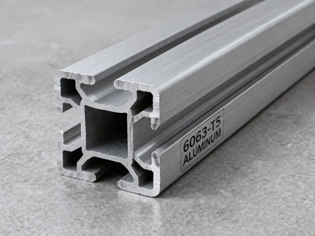
Heat Treatment Process and Mechanical Behavior
Beyond strength differences, T5 and T6 tempers affect the aluminum’s internal microstructure and overall behavior in service. The T6 process produces a more uniform and optimized distribution of strengthening precipitates, resulting in improved performance under sustained loads, cyclic loading, and environmental exposure. This makes T6 better suited for structural applications where long-term stability is critical.
In contrast, T5 temper results in lower internal stresses and better dimensional stability, reducing the risk of distortion in complex or thin extrusions. As a result, the choice between T5 and T6 is not only a matter of strength, but also of fabrication constraints, tolerance control, and long-term structural performance.
How Do You Convert Aluminum from T5 to T6 Temper?
Converting aluminum from a T5 to a T6 temper requires a full solution heat treatment cycle, and cannot be achieved through simple post-processing. The material must first be reheated to approximately 980°F to 1,020°F, allowing alloying elements to dissolve into a homogeneous solid solution. It is then rapidly quenched, typically in water, to retain this supersaturated structure. Finally, the aluminum undergoes artificial aging at lower temperatures to develop the strengthening precipitates characteristic of the T6 temper.
Comparison Between 6063-T5 and 6063-T6
Advantages of 6063-T5
-
Better dimensional stability after extrusion -
Lower residual stresses (no quenching) -
Easier to produce complex or thin profiles -
Typically lower manufacturing cost -
Good surface finish for architectural applications
Advantages of 6063-T6
-
Higher yield and ultimate strength -
Improved stiffness and reduced deflection -
Better performance in load-bearing applications -
Greater resistance to permanent deformation -
More efficient structural design (smaller sections possible)
Below you can see a comparison of base strengths between alloys and tempers. Please note that many factors affect the allowable design strengths used in design which goes well beyond this article.
| (KSI) | Ultimate Tensile Strength | Yield Tensile Strength |
| 6063-T5 | 27 | 21 |
| 6063-T6 | 35 | 31 |
| 6001-T6 | 45 | 40 |
In practice, both tempers are often used within the same system. T5 is commonly specified for architectural or secondary components where appearance and fabrication efficiency are prioritized, while T6 is preferred for primary structural members where strength and performance govern.
Engineering Implications and Design Considerations
From a structural design perspective, the choice between T5 and T6 involves a balance between strength requirements and fabrication constraints. The higher strength of T6 allows for increased load capacity, reduced member sizes, and improved performance under demanding conditions such as wind or impact loading. This makes it particularly well-suited for structural applications where deflection limits, connection forces, and overall efficiency are critical.
However, the quenching process required to achieve T6 can introduce internal stresses and geometric distortion, which may be problematic in applications requiring tight tolerances or complex cross-sections. In such cases, T5 provides advantages in terms of manufacturability, dimensional control, and cost efficiency. Engineers must also recognize that design values are governed by allowable stresses defined in the Aluminum Design Manual, not by nominal material strengths alone, and that temper selection directly impacts these allowable capacities.
CONCLUSION
The difference between T5 and T6 aluminum tempers is fundamentally driven by the heat treatment process, resulting in significant variations in strength, stiffness, and fabrication behavior. While T6 offers superior mechanical performance for structural applications, T5 remains a practical and efficient solution for applications where geometry, finish, and cost are the primary considerations. The correct selection depends on a comprehensive evaluation of loading conditions, fabrication constraints, and applicable design standards.
For your next project, ensure your design meets the highest standards of safety, performance, and code compliance. Contact Engineering Express to get plans, certification and expert support in structural analysis, connection design, and permitting-ready engineering for projects across the United States.
request a quote
chat or contact us
USEFUL ARTICLES
For guidance with your next project, explore our Plans, Calculators, Knowledge Base,
or contact us directly for site-specific support
VISIT OUR FULL PLAN STORE
Online Design Calculators
Visit Our Knowledge Base
Site specific project request
CHAT WITH A DESIGN engineer
CHAT WITH A DESIGN ENGINEER
Site specific project request
VISIT OUR FULL PLAN STORE
Online Design Calculators
Tell us how can we improve this post?
Understanding Canopies: Design and Load Considerations
A canopy is an overhead structure that offers protection from weather elements like rain, snow, and sunlight.
Canopies can come in various types and configurations, whether attached to an existing building or standing independently on their own supports.
With materials ranging from steel and concrete to aluminum, wood, or fabric, the design possibilities are extensive.
Designing canopies involves understanding specific considerations, especially when it comes to calculating the loads they must withstand.
This article will delve into the different types and layouts of canopies and the essential design factors to keep in mind.
For an easy way to estimate the necessary load requirements for your canopy design, see our ‘more help’ section below.
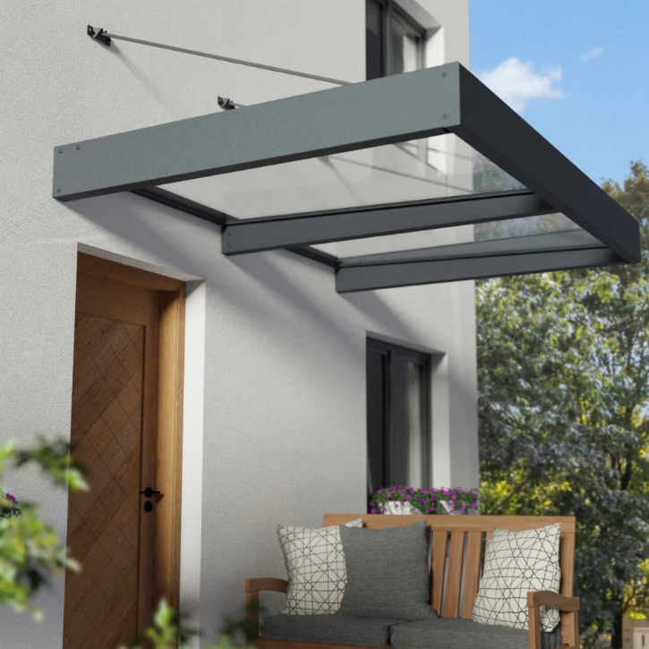
Basic Layouts of Canopies
Canopies can be categorized into two main types: freestanding canopies and host-attached canopies. Understanding these distinctions is essential for selecting the appropriate design for specific applications.
Host-attached
Host-attached canopies are structures connected to an existing building or structure. They can be further divided into two categories: those without posts, such as suspended, cantilevered, and retractable canopies, and those that incorporate posts for additional support. Suspended canopies are anchored to the host structure and hang freely, relying on strong cables or rods for support. Cantilevered canopies extend outward without vertical supports, requiring robust engineering to handle bending and shear forces while providing a sleek and unobtrusive design. Retractable canopies offer the flexibility to extend or retract the covering as needed, adapting to changing weather conditions. These designs provide various aesthetic and functional advantages while efficiently utilizing existing structures, offering tailored solutions to different architectural and environmental requirements.
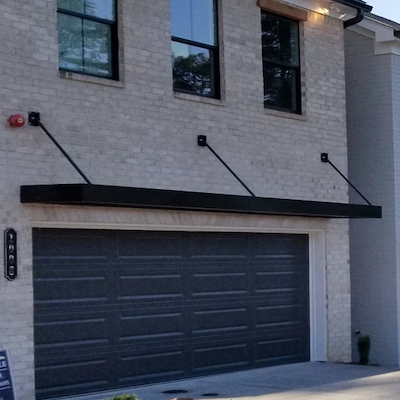
Suspended Canopy
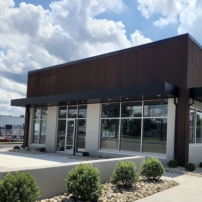
Cantilevered Canopy
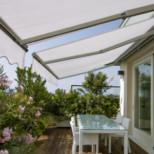
Retractable Canopy
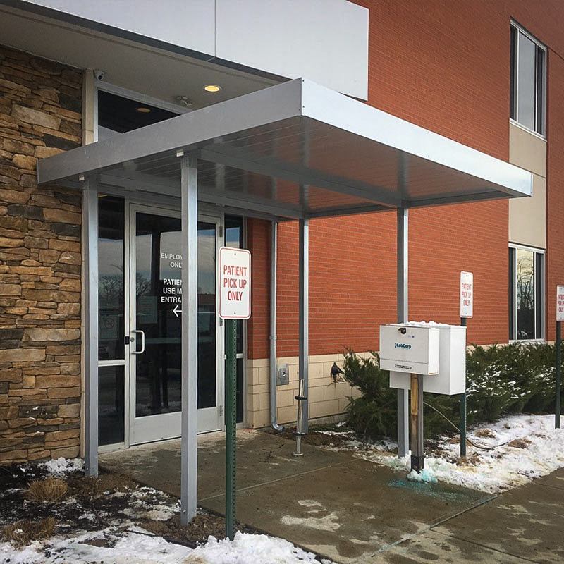
Post Supported Canopy
Freestanding
Freestanding canopies, on the other hand, are independent structures that do not rely on a host building for support. They come in many types, including shade canopies, pergolas, and awnings, each serving different purposes.
Freestanding Retractible Fabric Canopy

Elevated Freestanding Canopy
Types of Canopies
There are several types of canopies, each designed to meet different needs and preferences.
Fixed trellises are permanent structures that provide partial shade while allowing air to flow through and supporting climbing plants. They’re great for gardens and outdoor spaces where you want a natural look.
Mechanical or louvered sun control structures let you adjust the amount of sunlight and heat coming in by tilting or rotating the louvered panels. This feature makes them ideal for commercial buildings and outdoor areas that need flexible shading throughout the day.
Solid Insulated Roof Panels (IRP) offer excellent protection from the elements and help keep spaces comfortable, making them perfect for enclosed patios, outdoor dining areas, or commercial applications.
Finally, fabric canopies are lightweight and come in a variety of colors and styles, providing a stylish way to offer shade and protection from the weather. Each type of canopy has its own benefits, making it easy to find the right solution for your outdoor space!
Fixed trellises Canopy
Louvered sun control Canopy
Solid Insulated Roof Panels Canopy
Fabric Canopy
Use our complimentary canopy design calculator to determine your preliminary canopy design loads.
Use The CANOPY DESIGN CALCULATOR
Canopy Design: Meeting building codes standards
When designing and installing canopies, it is crucial to follow established building codes to ensure safety, durability, and compliance. The American Society of Civil Engineers (ASCE), the Florida Building Code (FBC), the International Building Code (IBC) and the International Residential Code (IRC) provide comprehensive guidelines and standards for the various types of canopies. These codes address critical factors such as load-bearing capacity, wind resistance, fire safety, and structural integrity. Understanding and implementing these regulations is essential for creating canopies that not only meet aesthetic and functional requirements but also uphold the highest safety standards. In this section, we will explore the key code requirements for different canopy designs, ensuring your projects are both compliant and reliable
Host attached conopies
When designing host-attached canopies, it is essential to follow the guidelines outlined in ASCE 7-16 Ch 30.11 / ASCE 7-22 Ch 30.9 for determining wind loads on these structures.
The design wind pressure is calculated using the formula p = qh.Kd.(GCp) (lb/ft2) , where qh represents the velocity pressure at the mean roof height, Kd is the wind directionality factor, and (GCp) is the net pressure coefficient specific to the canopy’s design.
The velocity pressure qh is evaluated based on the building’s height and its exposure category, which reflects the environment surrounding the structure.
The net pressure coefficients (GCp) provided in the code vary depending on the building height, with specific figures for buildings under and over 60 feet tall.
For buildings between 60 and 90 feet, interpolation between the relevant figures is permitted to ensure accurate calculations. These guidelines were first introduced in ASCE 7-16 and later expanded in ASCE 7-22 to include specific sections for buildings over 60 feet tall.
This is particularly important for host-attached canopies, as their design relies on the existing building’s support and how wind interacts with both structures.
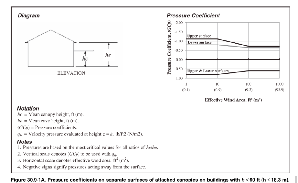
Freestanding canopies
Freestanding canopies are self-supporting roof structures, such as pavilions and walkway covers, designed according to the Open Buildings section of ASCE 7. To ensure their safety and stability, engineers assess wind loads by determining whether the wind flow is obstructed by permanent obstacles. The design process utilizes both Components and Cladding (C&C) and Main Wind Force Resisting System (MWFRS) guidelines. C&C focuses on wind pressures on the canopy’s surface, while MWFRS addresses the overall structural support against wind forces. For more details on when to apply C&C versus MWFRS wind loading, see ASCE 7 Main Wind Force vs. Components & Cladding Explained (MWFRS vs. C&C).
Trellises & Sunshades
Trellises and sunshades are unique structures characterized by their porous design, which allows wind, rain, and snow to pass through while effectively reducing sunlight exposure.
Due to their open configuration, these structures do not create a pressure differential between opposite sides of the roof surface. Consequently, they are designed according to the Other Structures and Building Appurtenances section of ASCE 7.
In this design process, wind pressures are applied both vertically and laterally to identify the least favorable loading conditions for the structure.
Additionally, trellises and sunshades must be engineered to withstand a concentrated load of 300 pounds applied at any point on the structure, simulating the weight of a maintenance worker standing on the roof surface. This ensures that they maintain structural integrity and safety under real-world conditions.
Fabric Awnings
Fabric awnings have special design rules that allow for flexibility when it comes to their structure and fabric. The framework of the awning can be designed with the fabric at a lower force, while the frame itself must be able to handle the full design load without the fabric. According to the FBC 3105.4.1, the structure shouldn’t rely on removing or adjusting the fabric during high winds (75 mph or more). For rigid awnings, the design must meet the loads in Chapter 16 of the code, but if the awning is meant to be taken down during strong winds, it should be able to withstand a wind speed of at least 115 mph and support a minimum roof live load of 10 pounds per square foot.
While ASCE 7 suggests a uniform load of 5 pounds per square foot and a concentrated load of 300 pounds for fabric structures, the FBC and IBC guidelines take priority. For fabric-covered structures, the wind load requirements vary based on whether the fabric is designed to be quickly removed or is permanent, with minimum wind speeds set at 105 mph for removable fabrics. The fabric must be securely attached to the frame, and there should be no rafters or front bars in the fabric pockets. Lastly, retractable awnings must be built to withstand both wind and live loads as described in Chapter 16, taking into account their open design to help reduce pressure and loads. For more detailed information, refer to the Florida Building Code section on Fabric awnings.
Sun control structucres
Sun control structures are becoming more popular in modern architecture, which is why they’ve been included in the Florida Building Code (FBC) 2023 8th edition. These structures help manage sunlight exposure, making spaces more comfortable and energy-efficient. According to the FBC, a sun control structure is an accessory structure with columns or posts supporting an open roof of girders, beams, or cross rafters. They can have fixed or adjustable louvers to control sunlight. The new FBC guidelines highlight the importance of these structures and their growing acceptance in other states.
The updated code introduces several important guidelines for the design and construction of sun control structures. One of the standout requirements is that all designs must meet specific wind resistance criteria based on risk categories. While this consideration is common across various outdoor structures, it is particularly emphasized for sun control structures due to their unique configurations and the potential risks they face in high-wind scenarios.
For instance, structures equipped with operable louvers have explicit mandates regarding their operation during severe weather. According to the FBC section 2002.8.2,
“Operable louvers shall be repositioned and locked in the vertical open position when wind speeds are predicted to be 75 mph (34 m/s) or greater. The contractor shall post a legible and readily visible permanent decal or sign stating words to the effect that the operable louvers are to be locked in the vertically open position when wind speeds are predicted to be 75 mph (34 m/s) and during a hurricane warning or alert as designated by the National Weather Service.” This requirement ensures proactive measures are in place to minimize wind damage.
To ensure the safety and functionality of sun control structures, the code highlights the importance of professional design oversight and adherence to electrical safety standards. Overall, these updates reflect a growing commitment to safety, compliance, and preparedness in construction practices, particularly in regions susceptible to high winds like Florida. For more detailed information, refer to the Florida Building Code section on Sun Control Structures.
The Evolution of Canopy Regulations
The regulations surrounding canopies have evolved significantly over time, reflecting advancements in engineering practices, safety standards, and environmental considerations. The Florida Building Code (FBC), the International Building Code (IBC), and the American Society of Civil Engineers (ASCE) continually update their canopy codes to address emerging challenges and enhance structural integrity.
ASCE 7-22 & the 2024 IBC / 2023 FBC
The recent updates to ASCE 7-22, the 2024 International Building Code (IBC), and the 2023 Florida Building Code (FBC) bring new changes to canopy design. These updates focus on improving the safety and strength of canopies in various weather conditions.
ASCE 7-22 has introduced updated wind speed maps, offering more precise estimates, especially for areas prone to hurricanes, like Florida’s western panhandle. These changes reflect increased wind speeds for Risk Categories I, II, and III buildings. The standard also adds new criteria for tornado loads, which are vital for maintaining the integrity of canopies in tornado-prone areas. Additionally, it revises wind pressure calculations for buildings with roof slopes greater than 7°, which impacts canopies attached to those structures.
The 2024 IBC builds on ASCE 7-22 by emphasizing that canopies and awnings must be designed to withstand various loads, including wind and lateral forces. A key improvement is the addition of guidelines to address uplift reactions, which are essential for keeping canopies stable during high winds.
The 2023 FBC aligns with ASCE 7-22 by incorporating the updated wind speed maps and tornado load criteria. This ensures that canopies and awnings in Florida are designed to handle the state’s specific wind conditions. The FBC also introduces new requirements for site-specific wind speeds, which provide more precise design criteria, especially helpful for coastal areas and regions with unique wind patterns.
These updates greatly enhance the safety and resilience of canopies and awnings compared to previous standards. With a focus on updated wind load provisions, site-specific wind speeds, and uplift reactions, the new guidelines ensure that canopies are better equipped to face extreme weather events, ultimately providing greater safety for users and infrastructure.
More Help
You can purchase an engineer-certified, pre-engineered performance evaluation for permit that have tables which convert wind speed to pressure for a variety of situations. There is a free sample available for inspection before purchase.
We also have an online calculator that provides more precise answers and can help with the design. Find the wind speed-to-pressure calculator by clicking here.
Article provided by Zachary A. Rubin, PE and updated by Chris Arbelbide. Additional fabric commentary by F. Bennardo PE
Tell us how can we improve this post?
The Updated Saffir-Simpson Scale
First, it needs to be said that there is a complicated formula that converts wind velocity to wind pressure. Many wind pressure values can exist from a single wind velocity which vary based on roof height, topography, terrain, even code version, and more.
The Saffir-Simpson Hurricane Wind Scale is a 1 to 5 rating based on a hurricane’s sustained wind speed (1 minute sustained speed, not wind gusts). This scale estimates potential property damage. Hurricanes reaching Category 3 and higher are considered major hurricanes because of their potential for significant loss of life and damage. Category 1 and 2 storms are still dangerous, however, and require preventative measures. In the western North Pacific, the term “super typhoon” is used for tropical cyclones with sustained winds exceeding 150 mph.
| Category | Sustained Winds | Types of Damage Due to Hurricane Winds |
|---|---|---|
| 1 | 74-95 mph 64-82 kt 119-153 km/h |
Very dangerous winds will produce some damage: Well-constructed frame homes could have damage to roof, shingles, vinyl siding and gutters. Large branches of trees will snap and shallowly rooted trees may be toppled. Extensive damage to power lines and poles likely will result in power outages that could last a few to several days. |
| 2 | 96-110 mph 83-95 kt 154-177 km/h |
Extremely dangerous winds will cause extensive damage: Well-constructed frame homes could sustain major roof and siding damage. Many shallowly rooted trees will be snapped or uprooted and block numerous roads. Near-total power loss is expected with outages that could last from several days to weeks. |
| 3 (major) |
111-129 mph 96-112 kt 178-208 km/h |
Devastating damage will occur: Well-built framed homes may incur major damage or removal of roof decking and gable ends. Many trees will be snapped or uprooted, blocking numerous roads. Electricity and water will be unavailable for several days to weeks after the storm passes. |
| 4 (major) |
130-156 mph 113-136 kt 209-251 km/h |
Catastrophic damage will occur: Well-built framed homes can sustain severe damage with loss of most of the roof structure and/or some exterior walls. Most trees will be snapped or uprooted and power poles downed. Fallen trees and power poles will isolate residential areas. Power outages will last weeks to possibly months. Most of the area will be uninhabitable for weeks or months. |
| 5 (major) |
157 mph or higher 137 kt or higher 252 km/h or higher |
Catastrophic damage will occur: A high percentage of framed homes will be destroyed, with total roof failure and wall collapse. Fallen trees and power poles will isolate residential areas. Power outages will last for weeks to possibly months. Most of the area will be uninhabitable for weeks or months. |
More Information
- About the Saffir-Simpson Hurricane Wind Scale (PDF)
- Saffir-Simpson Hurricane Wind Scale Extended Table (PDF)
- 2012 Revision to the Saffir Simpson Hurricane Wind Scale (PDF)
- Storm Surge & Scales (PDF)
Our Related Articles:
Wind Speed vs. Wind Pressure Explained
ASCE 7 Risk Categories Explained
Information From the National Hurricane Center, link here.
Tell us how can we improve this post?
How to Avoid Contact With Aluminum & Dissimilar Metals
This is provided to inform clients of the dissimilar metal protection requirements of the 2015 Aluminum Design Manual, Chapter M – Section M.7
Structures of the alloys covered by the Aluminum Design Manual are not ordinarily painted. Surfaces shall be painted where:
- 2014-T6 alloys are exposed to corrosive environments.
- Aluminum alloy parts are in contact with, or are fastened to, uncoated steel members or other dissimilar materials (see below).
- Exposed to extremely corrosive conditions.
- Required by the designer for reason of appearance.
Either the aluminum or the dissimilar material must be painted, sealed, or otherwise protected from contact with the following materials:
-
- STEEL
- Exceptions: No protection required for:
- Stainless Steel (300 series), except in high-chloride (salty) environments.
- Galvanized Steel (hot-dip galvanized or electro-galvanized).
- Aluminized steel.
- Acceptable Paints:
- Priming Paint (one coat), such as zinc molybdate, alkyd type primer in accordance with Federal Specification TT-P-645B (“good quality”, no lead content).
- Follow primer with two coats of paint consisting of 2 lb. of aluminum paste pigment (ASTM Specification D962-81, Type 2, Class B) per gallon of varnish meeting Federal Specification TT-V-8 1, Type 11, or equivalent.
- Severe Corrosion Conditions: Additional protection can be obtained by applying a suitable sealant to the faying surfaces, capable of excluding moisture from the joint during prolonged service in addition to the zinc molybdate, alkyd type primer.
- Exceptions: No protection required for:
- WOOD
- Includes aluminum laid on or against:
- Wood
- Fiberboard
- Other porous materials that absorb water and cause corrosion (i.e. where moisture is present and corrodents will be entrapped between the surfaces).
- Acceptable Protection:
- Heavy coat of alkali resistant bituminous paint or other coating providing equivalent protection before installation.
- Other insulating barrier between the aluminum and the porous material.
- Includes aluminum laid on or against:
- STEEL
-
- CONCRETE, Embedded into
- Exceptions:
- Concrete with no corrosive additives – no protection required.
- Where no extended exposure to extremely corrosive conditions is expected – no protection required.
- Acceptable Paints:
- Priming Paint (one coat), such as zinc molybdate primer in accordance with Federal Specification TT-P-645B (“good quality”, no lead content).
- Alt: Heavy coating of alkali resistant bituminous paint.
- Alt: Wrap aluminum with a suitable plastic tape applied in such a manner as to provide adequate protection at the overlaps.
- NOTE: Aluminum shall not be embedded in concrete to which corrosive components such as chlorides have been added if the aluminum will be electrically connected to steel.
- Exceptions:
- CONCRETE, Embedded into
-
-
- WATER that has come in contact with a heavy metal (e.g. copper)
- Heavy metals leached into water can cause corrosion of aluminum.
- Acceptable Remedies:
- Paint the heavy metal.
- Coat the heavy metal with plastic.
- Divert drainage from heavy metal away from aluminum.
- WATER that has come in contact with a heavy metal (e.g. copper)
-
Prepainted aluminum only requires additional protection when specified by the designer to abate extremely corrosive conditions.
Information provided by Zach Rubin, PE
Tell us how can we improve this post?
Why are spacing, edge distance, and embedment important for concrete anchors?
Why are spacing, edge distance, and embedment important for concrete anchors?
Anchors transfer loads into concrete, making them vital for safe design.
Their strength depends not only on the anchor itself but on how it interacts with the concrete.
Three factors are key: spacing, edge distance, and embedment depth. If these are not respected, the anchor may lose capacity and the concrete can crack, spall, or fail.
Understanding these details is essential for designing safe, durable, and code-compliant connections.
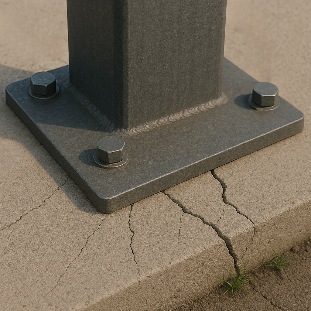
Spacing Between Anchors
Proper spacing between anchors is essential because concrete doesn’t behave like steel: it is strong in compression but weak in tension. When an anchor is loaded, it spreads stress into the concrete in the shape of a cone. If anchors are too close together, these cones overlap, which means the stresses combine and the concrete between them is forced to carry more tension than it can handle. This often results in splitting or premature cracking, and both anchors lose much of their capacity.
By providing adequate spacing, each anchor can develop its full pullout and shear strength, and the slab or foundation is able to distribute loads safely into the surrounding mass of concrete. This not only increases the reliability of the connection, but also prevents progressive failures, where the failure of one anchor weakens nearby ones.
A good rule of thumb is to keep at least 12 times the anchor diameter as spacing to the next anchor or to a concrete edge. Always check the manufacturer’s specifications for the exact values to use.
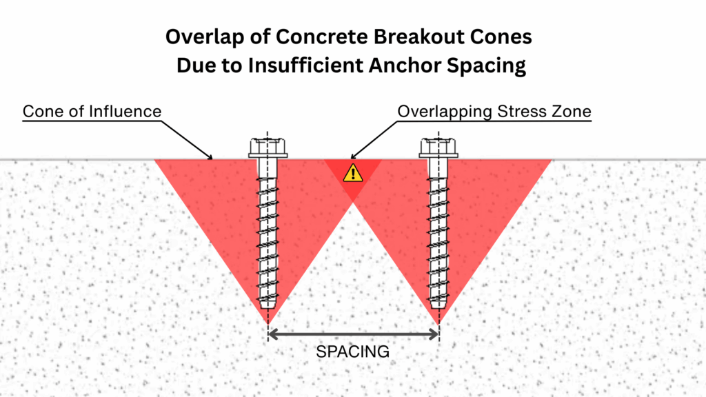
Edge Distance
The edge distance is the required spacing between an anchor and the closest free edge of the concrete. It plays a crucial role because the concrete around an anchor transfers the applied loads through a cone-shaped zone of stress.
If the anchor is installed too close to an edge, this cone cannot fully develop within the concrete mass. Instead, the stress zone is cut off, which makes the edge more vulnerable to cracking or spalling. In this situation, the anchor may fail prematurely, not because of the steel itself, but because the surrounding concrete cannot resist the concentrated forces.
Ensuring sufficient edge distance provides the anchor with enough material to distribute loads evenly, improving both the strength of the connection and the durability of the concrete element.
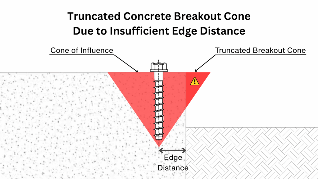
Watch a Demonstration of Edge Breakout !
Embedment Depth
The embedment depth is the distance an anchor is installed into the concrete, and it has a direct impact on its performance. As the anchor’s embedment decreases, the cone of influence becomes smaller, which reduces the amount of concrete engaged. This results in a noticeable decrease in both tensile and shear capacities compared to the maximum tested values.
To ensure proper performance, the concrete thickness must also be considered. A general guideline is that the slab or member should have a thickness of at least 1.5 times the anchor embedment depth. This prevents the breakout cone from extending beyond the bottom surface of the concrete and ensures that the anchor can fully develop its strength.
Providing sufficient embedment depth therefore allows the anchor to transfer forces into a larger volume of concrete, increasing both load resistance and long-term reliability of the connection.
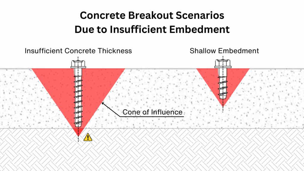
Other Factors That Influence Concrete Anchor Performance
While spacing, edge distance, and embedment are key parameters, several other conditions can also govern the final capacity of a concrete anchor.
These include:
• Anchor type (mechanical or adhesive/chemical)
• Concrete strength, including lightweight concrete considerations
• Slab thickness and support conditions
• Seismic loading and required safety factors
• Manufacturer-specific requirements
These factors can all impact anchor behavior and must be reviewed for each specific project.
Further Guidance
For safe and reliable design, it is important to go beyond general rules of thumb. Always consult the technical manuals provided by the manufacturer of the anchors you are using, or rely on specialized software that performs these calculations accurately. Most importantly, always consult a qualified design professional before installing any anchors that could affect the life and safety of the public or property.
Here are a few helpful resources:
• DeWalt Anchor Software – Technical Manual
• Hilti PROFIS Engineering – Technical Guides
• Simpson Strong – Technical Guides
For more detailed information and professional support on your future projects, don’t hesitate to contact us. If you have any questions or want to learn more about our services, simply get in touch—click the buttons below to get started.
Also, make sure to check out our other engineering articles for more valuable insights and tips!
For more detailed information and guidance on handling your future design projects, check out our online design calculators, contact us for site-specific projects, or reach out to us with your inquiries.
Online Design Calculators
Site specific engineering request
Contact us
Tell us how can we improve this post?
Is Steel or Reinforcing or Fibermesh Required in Posts & Footings of Building Components?
INTRODUCTIONThe main purpose foundations serve is to distribute and resist the forces or loads experienced by the host structure due to wind, rain, snow, seismic, & other load conditions. When it comes to building components such as generators, signs, and fences the code leaves a gray area for foundation design. This happens because most building components are non-habitable by and therefore aren’t at the forefront of thought when code requirements are established. This article summarizes our research regarding which footing situations steel reinforcement is not needed when designing building components and provides some alternate reinforcing methods for design.
TO REBAR OR NOT TO REBAR? The ACI 318-14 manual is the leading standard when it comes to concrete design. Chapter 2 of ACI 318-14 gives us the definition for plain concrete: “concrete, plain—concrete with no reinforcement or with reinforcement less than the minimum amount specified for reinforced concrete.” As mentioned, the definition of plain concrete doesn’t necessarily mean it doesn’t have any rebar present, it just means it has less rebar than specified amount for its selected use. For the purposes of this article we will assume that plain concrete lacks any and all reinforcement. Continuing to Chapter 14 of ACI 318-14 we finally get a scope of us for “plain concrete” and what are some cases in which plain concrete is permitted: · “14.1 – Scope This chapter shall apply to the design of plain concrete members, including (a) and (b): (a) Members in building structures (b) Members in non-building structures such as arches, underground utility structures, gravity walls, and shielding walls” · “14.1.3 – Plain concrete shall be permitted only in cases (a) through (d): (a) Members that are continuously supported by soil or supported by other structural members capable of providing continuous vertical support (b) Members for which arch action provides compression under all conditions of loading (c) Walls (d) Pedestals”
· “14.1.4 Plain concrete shall be permitted for a structure assigned to Seismic Design Category (SDC) D, E, or F, only in cases (a) and (b): (a) Footings supporting cast-in-place reinforced concrete or reinforced masonry walls, provided the footings are reinforced longitudinally with at least two continuous reinforcing bars. Bars shall be at least No. 4 and have a total area of not less than 0.002 times the gross cross sectional area of the footing. Continuity of reinforcement shall be provided at corners and intersections. (b) Foundation elements (i) through (iii) for detached one and two-family dwellings not exceeding three stories and constructed with stud bearing walls: (i) Footings supporting walls (ii) Isolated footings supporting columns or pedestals (iii) Foundation or basement walls not less than 7-1/2 in. thick and retaining no more than 4 ft of unbalanced fill.”
Reading through the permitted cases for non-reinforced concrete, the bolded ones are the ones that apply the most to building components. Beginning with the broadest case; “14.1–Scope: …(b)”, this case covers most building components, only being limited on a case specific basis. ACI 318-14 then continues to give us other situations in which plain concrete is permitted IS “14.1.3-(a)“. These definitions can be applied to many building components such as sunshades, overhangs, exterior building decorations attached to the building (for aesthetic purposes), posts, etc. Also, it lays the framework for isolated footings not related to family dwellings or any habitable spaces, the phrase that covers this is “(a) Members that are continuously supported by soil…”. So in accordance with ACI, if the footing is continuously supported by soil it is okay to be designed as plain concrete, more on this topic later in the article. The last applicable allowable case specified by ACI is “14.1.4-… (b)”. This case can be applied to any footings used to for large or small fences, canopies, generators, or any other non-building structures that may need footings. Commentary provided on this section gives us the reason on why plain concrete is allowable in such limited cases. To summarize the commentary since the capacity of plain concrete is directly correlated to the compressive strength, size, and other properties plain concrete should be reserved only for uses in which the concrete will primarily be: in compression, needed to tolerate random cracks without detriment to its structural soundness, and is expected to have low ductility since it is not an essential design feature.
Overall, you must calculate the worst load combination experienced by the proposed member. ASCE 7 gives us our basic load combinations which also correspond to Florida Building Code Seventy Edition (2020) Section 1605.3. The concrete foundation must have the capacity to handle the axial, self-weight, uplift and sliding forces & the overturning moments by a factor of safety of 1.5,I f the worst load combination is not 0.6W + 0.6D. If the worst load combination is 0.6W + 0.6D then the concrete foundation must handle the before mentioned forces by a factor of safety of 1.67. Keep in mind this is only applicable if wind is your governing load case, if not this factor of safety is subject to change in accordance with the governing load. The foundation must also meet the criteria in ACI 318-14 sections 14.1, 14.1.3, and the seismic category that the slab falls within the categories mentioned in section 14.1.4. If you believe your slab will take high shear forces due to temperature or shrinkage fiber reinforcement is recommended, or if the footing will experience any high-tension loads rebar is recommended. This should be checked by the EOR or designer.
CONCRETE POST FOUNDATIONS Quick note regarding plain concrete post footings and their limitations. Per International building code (2018), if a footing is geographically located in an area where the frost line is zero inches a patio cover shall be permitted to be supported on a concrete slab, on grade without footings, provided that the slab follows provisions in Chapter 19 of International Building Code (2018) and that the slab is not less than 3.5 inches thick. The columns may not support loads in excess of 750 pounds (3.36kN) per column.
FIBER-REINFORCED CONCRETE This leads us into our next section, what is fiber reinforced concrete (FRC)? ACI defines it in their ACI318-14 manual as mainly concrete reinforced with steel fibers, but Fiber reinforced concrete (FRC) is concrete containing fibrous material which increases its structural integrity. Fibers are usually short, discrete, and are uniformly distributed and randomly oriented. Fiber material may vary from steel to glass, and even synthetic or natural fibers. ACI318-14 covers this in CH 7. Table 7.6.1.1 gives us a minimum required area of steel or “wire-reinforcement” for non-prestressed one slabs. As seen below it gives us a formula for reinforcement needed based on the gross cross-sectional area of the concrete slab and its yield strength. Why use FRC? Reinforcing concrete with fibers is less expensive than hand-tied rebar, while still increasing the tensile strength many times. The fibers can be circular or flat, and they are often described by a convenient parameter called “aspect ratio”. The aspect ratio is the ratio of its length to its diameter. Typical aspect ratio ranges from 30 to 150. The fibers help concrete in a very similar matter as rebar does. Since the modulus of elasticity of the fibers is higher than the concrete, they help support the forces experienced by the structural member by increasing the tensile strength of the member. Increasing the aspect ratio of the fibers usually leads to an increase in the flexural strength and toughness of the member, but if the fibers are too long, they can contract and create a “balling up” effect in the concrete mix and become workability problems. Fiber reinforcement has one more benefit that hasn’t been concluded yet and it is that it may improve concretes’ freeze thaw resistance. A fibermesh ratio of 0.1%/cuyd is typically seen in the industry for smaller building component applications. FRC & FORST/THAW RESISTANCE
There was a study conduct by Cantin and Pigeon, and Pigeon et al. The study concluded that the incorporation of steel fibers with a length between 54 mm – 60 mm (2 – 2.5 in.) do not have a significant influence on the concrete resistant to surface scaling. In contrast incorporating short fibers with a length of 3 mm reduced the amount of concrete degradation. Now while this study shows these results there are some other studies it references within that show the opposite. Overall this benefit, in our opinion for the time being, remains inconclusive. For more information regarding rebar requirements please visit ACI-360 & ASCE 7
Sources: https://www.asce.org/uploadedFiles/Newsroom/Content_Pieces/asce-fact-sheet.pdf https://alleghenydesign.com/fiber-reinforcing-in-concrete-slabs/ https://theconstructor.org/concrete/fiber-reinforced-concrete/150/ https://www.britannica.com/biography/Joseph-Monier https://www.giatecscientific.com/education/the-history-of-concrete/ https://csengineermag.com/article/clearing-the-confusion-on-plain-concrete/ https://engineeringexpress.com/wiki/frost-protection-concrete-footings-grade/ https://www.sciencedirect.com/science/article/pii/S1877705815013144 https://en.wikipedia.org/wiki/American_Concrete_Institute https://en.wikipedia.org/wiki/Fiber-reinforced_concrete
An article authored by Francisco Sarmiento of Engineering Express 5/2019 |
 Section
 Tell us how can we improve this post?
ASCE 7 Main Wind Force vs. Components & Cladding Explained (MWFRS vs. C&C)

ASCE 7 separates wind loading into three types: Main Wind Force Resisting System (MWFRS), Components and Cladding (C&C), and Other Structures and Building Appurtenances.
MWFRS is defined as “(a)n assemblage of structural elements to provide support and stability for the overall structure.” Typically, members that receive loading from two surfaces are designed to resist MWFRS loading. Let’s say you had a steel moment-resisting frame building with metal roof and wall panels as pictured above, you would design the moment frames and the spread footings at the base of the frames to resist MWFRS loading from the lateral wind pressure on the wall panels and positive/negative wind pressure on the roof panels.
C&C is defined as “elements of the building envelope that do not qualify as part of the MWFRS.” Let’s take the metal building again shown above as an example. The metal roof and wall panels would be considered cladding. The overhead door, walk door, and window would be considered components. Also, the roof purlins and wall girts are receiving loading from the cladding and are, therefore, also considered components. The wind pressure then varies on these components and cladding based on their respective effective wind area.
Other Structures and Building Appurtenances are defined as “rooftop structures, rooftop equipment, solid freestanding walls, freestanding solid signs, chimneys, tanks, open signs, lattice framework, and trussed towers”. Let’s say we were to add a rooftop-mounted mechanical air conditioning unit to the roof purlins of our metal building; we would use this section of the code to determine the appropriate wind loading on the mechanical unit itself.
Our Commentary:
Think of MWFRS as ‘what happens to the balloon’ – it could slide, fly up, or flip over in wind. We look at the unit and consider effects as a whole.
Components & cladding consider the effects of smaller ‘bursts’ of wind that occur in any given part of the building, not paying attention to the structure as a whole.
Both must be reviewed for a structure’s integrity.
Components & cladding are a function of the area of consideration – the probability that Mother Nature will blow her full fury at all places …at the same time… So think of a door opening. There’s more of a chance that the area near the lock gets a maximum 3-second burst in that one area than the whole door, so the tributary area is smaller, but the pressure is higher. The door is more likely to receive its tributary area of a 3-second burst than the door + sidelites + transom, so the frame as a unit has a slightly lower pressure than its parts.
Taking this up to the entire structure (beyond 100sqft per ASCE 7) approaches MWFRS pressures which also have to be looked at from windward directions, leeward directions, and combinations thereof with multipliers of pressure at given areas. It’s not easy, and the designer must purchase & study ASCE 7 and review the range of software applications to assist with design. Have a thorough understanding before construction, or contact us to help.
Tell us how can we improve this post?
Types of At-Grade Footings Explained
Choosing the Right Footing for Patios, Pergolas, and Sunrooms
Every great structure begins below the surface. For sunrooms, pergolas, carports, and patio covers, the footing is what carries the load. Different footing designs manage forces in their own way, and choosing the right type is the key to stability against wind, weight, and shifting soils.
1. Isolated Footings – The “Single Post” Foundation
An isolated footing is the simplest type of support: one post, one pad of concrete. It can be round, square, or rectangular, and it stands on its own. That means it has to do a lot of heavy lifting—resisting wind pushing sideways, gravity pulling down, and uplift forces trying to pull it out of the ground. In wet, saturated soils, isolated footings lose strength quickly because there is so little else for the footing to be supported by.


2. Ribbon Footings – The “Continuous Strip”
A ribbon footing is another term for a continuous strip footing or one long isolated footing. Frequently used in signs and patio structures with pavers, ribbon footings suffer less from torsional and eccentric loading due to their profiles, but must still be large enough or have secondary bracing to resist overturning forces from lateral pressures such as wind, especially in saturated soils.
Constrained vs. Non-Constrained Footings
Footings can be constrained or non-constrained.
A slab or foundation above a footing (constrained) locks it in place, improving resistance to wind and uplift.
Stand-alone footings may need to be bigger to achieve the same strength.


3. Thickened Edge Slabs
A thickened edge slab has extra depth along its borders, creating built-in reinforcement that supports posts against both gravity and uplift. Building codes specify minimum footing dimensions for these patio slabs, while larger thickened edges are often used as the foundation for full slabs on grade with integrated support.
Embedded vs. Surface-Mounted Posts
Posts can be surface mounted or embedded into the foundations to achieve different results. An embedded post typically takes more uplift and overturning forces and resists bending/listing which is useful for design of lateral and uplift forces.


4. Additional Foundation Considerations
Other foundation types—like stem walls or pile-supported systems—exist but fall outside the scope of at-grade footings. What matters is that different foundation types can settle differently over time, so mixing them should be done with care. In colder regions, frost protection may also come into play: some footings must extend below the frostline to prevent heave., though patio-type projects are often exempt. Always check your local codes and confirm requirements with a building official or licensed professional engineer before construction.
For guidance with your next project, explore our Plans, Calculators, Knowledge Base,
or contact us directly for site-specific support
Visit Our Plan Store
Online Design Calculators
Visit Our Knowledge Base
Site specific project request
Chat with a Designer
Tell us how can we improve this post?
What Seismic area is my location?
Here are some useful sites to check the seismic criteria for a location:
https://www.fema.gov/earthquake-hazard-maps
https://earthquake.usgs.gov/hazards/designmaps/ – USGS
https://www.seaoc.org/page/seismicdesignmaptool– Structural Engineer Association of California
Tell us how can we improve this post?
How to Find Wind Speed & Snow Using the ASCE and ATC Hazards Tools by Location Websites
The 2 Ways To Find Wind Speed, Snow & Related Values For Projects in the US
There are currently two websites as of January 2024 that allow access to finding a location’s ASCE wind speed, snow load, as well as other code minimum requirements.
This article helps you find and navigate each site.
Method 1:
ASCE Hazard Tool – For Answers using ASCE7-22
Method 2:
ATC Hazards By Location – For Answers using ASCE7
pre-2022
Method 1: ASCE Hazard Tool (using ASCE 7-22)
Use ASCE 7-22 for the 2023 Florida Building Code and as required by your project or local municipality.
The ASCE Hazard tool provides detailed information not only on wind speed and snow but also code minimun values by location for:
– Seismic
– Ice
– Rain
– Flood
– Tornado
Using the tool is easy. Visit the ASCE Hazards tool and enter the project address.
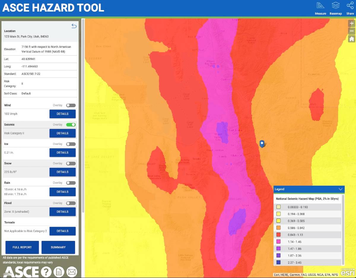
The ASCE Tool provides a quick summary of minimum values as well as the ability to download a full report of findings.
All of this is with no cost or login.
NOTE: Values obtained are code-minimum, meaning your local jurisdiction, developer, or insurance company may require values HIGHER than the answers provided. Always confirm the proper use of minimum loads before designing & constructing any structure from the results from these tools.
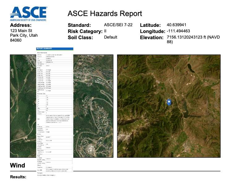
Method 2 (for older codes): How to Find Wind Speed & Snow Using the Applied Technology Council Hazards (ATC Hazards) by Location Website (Pre ASCE 7-22)
This method generally applies to the 2021, 2018 International Building-Residential codes and related codes including the 2020 Florida Building Codes.
Always check with the local municipality & lead project designers to select the appropriate minimum design criteria.
The Applied Technology Council (ATC) offers site-specific information that is used in our calculators to determine wind velocity. For the best results, the address of the site may be used. To find your wind speed, follow the step-by-step guide below.
Note: Ground Snow Load can also be found in this tool, as well as Seismic information.
Step 1 ATC Hazards:
Navigate to https://hazards.atcouncil.org/#/
Step 2 ATC Hazards:
Enter your address, zip code, or city and state in the search bar and press the search button.
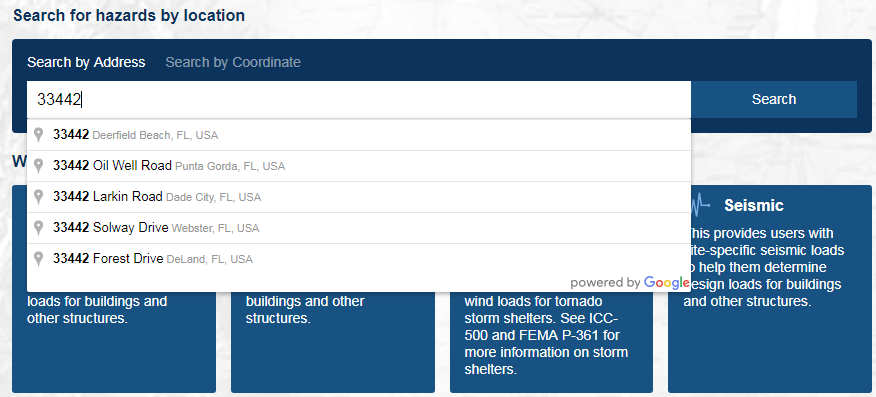
Step 3 ATC Hazards:
On the left side of the screen, check that the “wind” tab is selected.
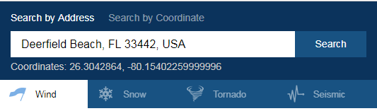
Step 4 ATC Hazards:
Determine your wind speed based on your Risk Category. Wind speeds may differ depending on if ASCE 7-05, ASCE 7-10, or ASCE 7-16 is being used. If you are unsure, please check with an Engineering Express Technician.
Step 5 ATC Hazards:
Using the ASCE 7-10 definitions for Risk Categories I-IV:
-
-
- Use Risk Category I for “buildings and other structures that represent a low risk to human life in the event of failure.” Such as
Buildings and other structures that represent a low hazard to human life in the event of failure, including but not limited to Agricultural facilities, certain temporary facilities, minor storage facilities, fences, gates, etc. - Use Risk Category II for “all buildings and other structures except those listed in Risk Categories I, III, and IV.” Such as canopies or pergolas. Most Engineering Express calculators will ask for Risk Category II wind speeds.
- Use Risk Category I for “buildings and other structures that represent a low risk to human life in the event of failure.” Such as
- To use Risk Category III, contact Engineering Express for a site-specific design. Use Risk Category III for “buildings and other structures, not included in Risk Category IV, with potential to cause a substantial economic impact and/or mass disruption of day-to-day civilian life in the event of failure; buildings and other structures not included in Risk Category IV (including, but not limited to, facilities that manufacture, process, handle, store, use, or dispose of such substances as hazardous fuels, hazardous chemicals, hazardous waste, or explosives) containing toxic or explosive substances where their quantity exceeds a threshold quantity established by the authority having jurisdiction and is sufficient to pose a threat to the public if released.”
- To use Risk Category IV, contact Engineering Express for a site-specific design. Use Risk Category IV for “buildings and other structures designated as essential facilities; buildings and other structures, the failure of which could pose a substantial hazard to the community; buildings and other structures (including, but not limited to, facilities that manufacture process, handle, store, use, or dispose of such substances as hazardous fuels, hazardous chemicals, or hazardous waste) containing sufficient quantities of highly toxic substances where the quantity exceeds a threshold quantity established by the authority having jurisdiction to be dangerous to the public if released and is sufficient to pose a threat the public if released; or buildings and other structures required to maintain the functionality of other Risk Category IV structures.”
-
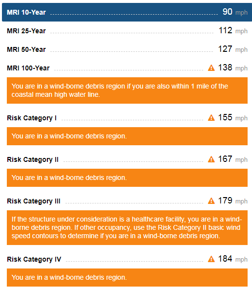
Works CitedEngineers, American Society of Civil. Minimum Design Loads for Buildings and Other Structures (ASCE Standard). American Society of Civil Engineers, 2010, 2022“Hazards by Location.” ATC Hazards by Location, Applied Technology Council, https://hazards.atcouncil.org/.ASCE Hazards Tool, https://ascehazardtool.org.
What are porosity and closure angles when defining a porous building opening?
Explanation:
In the event of a high wind event, it is the concern of building codes ASCE-7 and ASTM specifications that windows and doors don’t fail and develop an opening breach in the building. An opening would allow more wind to enter the structure and pressurize the inside of the building, leading to other doors and windows blowing out, the roof lifting, etc. This is also known as developing a ‘partially enclosed’ building condition in ASCE-7.
In order for an opening to remain classified as ‘non-porous’, the opening must not allow an excessive wind amount to enter the building. This includes even after the window glass breaks or door swings open and the opening is protected by an impact protection system (shutter, fabric, etc.).
The Code:
Per ASTM 1996, section 3.2.11 (2014a), an opening is defined as porous when the open area of an assembly exceeds 10% of its projected surface area.
ASTM 1996 goes on to say that this porosity factor is defined as the design wind force (per ASCE-7) divided by the horizontally projected area of the entire assembly.
A reference for more information can be found from this FEMA Publication or by purchasing ASTM 1996.
ASCE 7-10 has this to say in the matter in the commentary:
C26.10 ENCLOSURE CLASSIFICATION
The magnitude and sense of internal pressure is dependent upon the magnitude and location of openings around the building envelope with respect to a given wind direction. Accordingly, the standard requires that a determination be made of the amount of openings in the envelope to assess enclosure classification (enclosed, partially enclosed, or open). “Openings” are specifically defined in this version of the standard as “apertures or holes in the building envelope which allow air to flow through the building envelope and which are designed as “open” during design winds.” Examples include doors, operable windows, air intake exhausts for air conditioning and/or ventilation systems, gaps around doors, deliberate gaps in cladding, and flexible and operable louvers.
[It is the interpretation of Engineering Express from these standards and our test lab & field expertise that openings are not perpendicular to the surface but must consider wind entry from any possible wind direction.]SOLUTIONS:

When storm panels are applied to a structure, they frequently develop openings that can create a porous condition. Examples include when corrugated storm panels are built out from a structure for anchorage or separation from glass purposes, turn a corner, etc. For this reason, closure panels are typically designed to restore the opening down to below 10% porous. Closure angle examples are illustrated here which comes from our digitally assisted product approval FL28390 which assists in better calculating anchorage and separation from glass requirements.
Tell us how can we improve this post?
About Lag Bolts-Screws In Wood – Size – Pullout – Shear
Lag screws are some of the toughest types of screws available. When it comes to fastening heavy materials in construction and woodworking, lag bolts and lag screws stand out as some of the most reliable and commonly used fasteners.
In this article, we’ll take a closer look at why they’re so widely used, exploring their uses and features. We’ll also discuss building code specifications for lag screws, covering their engineering uses and how to meet industry standards.
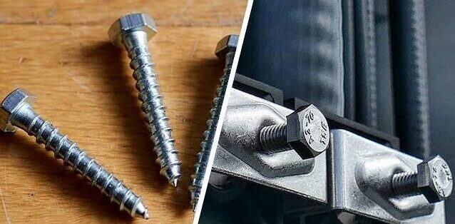
Understanding Lag Screws
Lag Screws vs Lag Bolts
Lag screws and lag bolts are terms frequently used interchangeably, but they actually refer to the same type of fastener. The terminology can vary by region and industry; for example, “lag screw” is often preferred in woodworking contexts, while “lag bolt” is more commonly used in construction. However, the most accurate term is “lag screw,” as it correctly reflects the fastener’s design, which does not require a washer or nut.
Why choose Lag Screws?
Lag screws are primarily used for fastening wood, thanks to their self-tapping design that allows them to create strong connections without needing to pre-drill holes in most cases. However, larger lag screws may require pre-drilling to ensure proper installation. They are sturdy, tough, and reliable, making them a favorite in construction and woodworking projects. You’ll often find lag screws used to secure timber beams, build decks, and assemble heavy-duty furniture where strength is essential. Their coarse threads grip the wood tightly, ensuring that everything stays stable and reduces the risk of loosening over time.
While lag screws can work with other materials like metal and concrete, they shine the most when used with wood. Many of them also come with protective coatings to prevent rust, making them perfect for outdoor projects exposed to moisture and weather. Overall, lag screws are a dependable choice for anyone looking to create durable, long-lasting connections in their building projects.
Design features
Lag screws are designed with distinct features that enhance their performance as heavy-duty fasteners. They typically have a hexagonal head, which allows for easy installation using a wrench or socket, providing the necessary torque to securely drive the screw into the material. One notable characteristic is that the threads on lag screws are coarse and often do not extend all the way to the head. This design allows the screw to grip the material effectively while providing a smooth, unthreaded section near the top, which can help prevent splitting in the wood and allows for a better fit in certain applications. The pointed tip enables lag screws to penetrate wood easily without the need for pre-drilling, streamlining the installation process.


Lag Screws vs Wood Screws
Lag screws have significant advantages over regular wood screws, especially when it comes to handling heavy loads and creating strong connections. While regular wood screws have finer threads and are designed for lighter tasks, lag screws boast coarser threads and a thicker shaft, which helps them grip the material more securely. This makes lag screws perfect for jobs that need extra strength, like securing large beams or heavy structural connections. Plus, their hexagonal head allows you to use a wrench for greater torque during installation, whereas regular wood screws are typically installed with a screwdriver. In summary, if your project requires enhanced durability and the ability to bear heavy loads, lag screws are the way to go, while regular wood screws are best for everyday tasks.
Lags in use
Using lag screws to fasten sheathing to multi-ply wood columns can be tricky, especially when it comes to positioning the screws in relation to the edges of the wood. This placement is crucial because it affects the screw’s performance, as outlined in the NDS (National Design Specification) tables 12.5.1A, 12.5.1C, and 12.5.1E, which detail the minimum edge and end distances required for proper installation. A key concern with larger diameter bolts is the risk of splitting the wood before the load can shift to other bolts that are less heavily loaded. For example, when using lag bolts in tension on a narrow face of a 2x wood piece, table 12.5.1E indicates that you need to maintain an edge distance of 1.5 times the diameter of the screw and an end distance of 4 times the diameter. So, for a ½-inch diameter lag screw, you should have a minimum edge distance of ¾ inch. This ensures that the fastening is effective while also protecting the wood’s integrity.
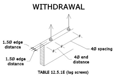
When using lag bolts in shear with loads parallel to the grain on the narrow face of a 2x wood piece, you’ll want to pay attention to the edge and end distances outlined in the NDS tables. According to table 12.5.1C, the minimum edge distance should be 1.5 times the diameter of the fastener, while table 12.5.1A suggests that the minimum end distance can range from 2 to 3.5 times the diameter. For a ½-inch diameter lag screw, this means you need at least a ¾-inch edge distance. Following these guidelines ensures that the lag screws can be used effectively while maintaining the wood’s integrity under shear loads.
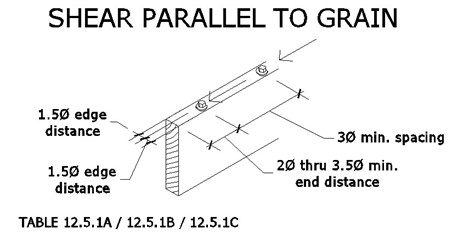
The situation changes when the same lag bolt is loaded perpendicular to the grain. According to table 12.5.1C, the edge that bears the load needs to have a minimum distance of 4 times the fastener diameter. For a ½-inch lag bolt, this means you need at least 2 inches of edge distance, while a 3/8-inch lag bolt requires 1.5 inches. This requirement exceeds the ¾-inch edge distance that would be available if you were able to center the fastener in the narrow face of the 2x wood. This highlights the importance of careful planning when placing lag bolts to ensure they meet the necessary structural guidelines.
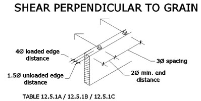
To understand how to position lag screws effectively, it’s important to distinguish between the loaded and unloaded edges of the beam (or stud, in this case). The loaded edge is the side that faces the direction of the force, while the unloaded edge is the opposite side.
For more detailed information, the NDS provides specific guidelines on end distances, edge distances, and other critical designs for lag bolt connections.
Now that lag screws hold no secrets for you, we wish you the best of luck with your upcoming projects! If you have any questions about wood design or need engineering assistance, simply click the button below to get in touch with us. Don’t forget to explore our other engineering articles on our website for more valuable insights and tips!
Contact us with your wood connection needs to discuss our innovative engineering solutions
SEND ENGINEERING EXPRESS A MESSAGE
Tell us how can we improve this post?
ASCE Wind Speed Risk Category To Use with Signs – Fences & Building Components On-Off Buildings
This topic has been merged with our main ASCE 7 Risk Category Knowledge Base Article.
See this page and scroll to the bottom for an explanation of deciding which risk category to be used with signs & fences.
Glossary of Engineering Terms
Glossary of Building Component Engineering Terms & Abbreviations
These terms are published by Engineering Express to coincide with help menus for our online tools & published articles and as they relate to the Building Component Design industry.
See also our FLOOD ENGINEERING GLOSSARY for more terms related to flood engineering.
See Also SUNROOM TERMINOLOGY for a list of Sunroom terms compliments of the National Sunroom Association
Looking for our list of abbreviations?
Contact Us for any questions, clarifications, or suggestions you have regarding these items.
Glossary
| LABEL | DEFINITION |
| ADDITION ROOF TYPE | For sunroom enclosures, roof types can be monoslope for studio, shed, or other single slope style roofs or gable, also known as A-Frame. Roof type & slope affects the conversion from wind speed to pressure Learn More. |
| ATTACHED TO HOST | For our column calculators, Yes assumes pinned at top & bottom so k=1.0 and simply supported for lateral bending moment on post itself No assumes fixed at base and pinned at top (such as for freestanding aluminum structures, k=2.0 for buckling & cantilever moment for lateral on post itself) |
| AHJ | AHJ – Authority Having Jurisdiction. The entity with the authority to determine / enforce building code requirements. Typically the building department you submit permits to. |
| ASCE | American Society of Civil Engineers. A professional body that provides much of the structural engineering provisions present in the Florida and International Building Codes. Visit asce.org for more. |
| ASD (PRESSURES) | Allowable Stress Design – where the capacity of the member in question is reduced (factored down) to an allowable factored limit as opposed to ultimate pressures where the load is factored up and compared to actual capacities. |
| BEAM ALLOWABLE SPAN | Clear Beam Span of the panel or member in question between two supports. |
| BENDING STRESS | The total bending stress from a transverse force in the extreme fibers of the member in question. |
| BUILDING ENVELOPE | Simply defined, it’s the separation between the interior & exterior of a building/habitable space or air-conditioned vs. non-air-conditioned space. The ‘shell’ of a building. The building envelope is subject to ‘internal pressurization’, affecting building components that comprise the building shell. |
| CLASSIFICATION | Screened for removable acrylic sliders, open if 3 or more sides are open, solid for glass or panels. |
| CLEAR SPAN | The clear distance between supports of a member in question. |
| CLEARANCE HEIGHT | Used in our mechanical rooftop equipment calculator, typically defined by this firm as the support structure clear height, or height from grade/roof level to the bottom of the unit in question. Seek confirmation from the associated unit diagram before using this definition. |
| CODE YEAR | Select ASCE 7-16 in our online calculators only for the 2020 Florida Building Code or 2018 International Building Code (IBC). ASCE 7-10 corresponds to ASCE 7-10 and codes before IBC 2018. |
| COLUMN ALLOWABLE HEIGHT | The allowable clear span of a post from the slab to beam or knee brace above. If the resulting allowable height in a result is less than the allowable ceiling height, the result shall include knee walls or other supporting structures. |
| COLUMN SPACING | For the determination of column loads, the column spacing is the average on-center spacing between columns, in decimals for our online tools (0.5= 6”). For the determination of carry beams between columns, spacing is the clear span between two columns. Typically column spacing is the on-center spacing of columns unless otherwise defined. |
| COMPRESSIVE STRESS | The stress from a longitudinal force acting in compression on a member axially, typically for a column. |
| COMBINED STRESS UTILIZATION | See Utilization |
| COMPONENTS & CLADDING | The pieces and parts of a building or other structure that comprise the building envelope. Typical component & cladding items include windows, doors, door handles & hinges, exterior fascades, etc. ASCE-7 has specific requirements for the design of building components & components of other structures. |
| CRITICALLY WELDED | When aluminum is heated during welding, the alloys realign and weaken the member, typically within 2 inches of any heated surface. For our calculators, if a beam or column is welded at any critical point within 2 inches of the maximum moment, select ‘yes’ which loads an alternately calculated allowable stress for the aluminum selected. Click here for more on the topic. |
| DEAD LOAD (D) | Dead load is the actual self-weight of an unloaded roof, floor, or similar surface. Typically the load of sunroom roof panels, or roof trusses + underlayment + shingles or tiles, or for decks the weight of wood + connectors. |
| DEFLECTION | The bending limit of a member – see chapter 16 of the building code, typically L/180 for glass, L/60 for screen, L/240 for plaster. Click here for more. Deflection is typically expressed as L/# where L = the Clear Span of the member in question. For example, a member with a 10’ long clear span that has an allowable deflection limit of L/60 would be allowed to deflect 10/60= 0.1667’ or 2”. |
| EFFECTIVE WIND AREA | Effective wind area is the area of the building surface used to determine (GCp). This area does not necessarily correspond to the area of the building surface contributing to the force being considered. There’s an H*H/3 rule & structural break understanding to better understand. Click here to read more. |
| ELEVATION ABOVE SEA LEVEL (ELEVATION FACTOR, Ke) | A variable used in wind load calculations that allows for reductions in the calculated wind load as site elevation above sea level increases. For Every 1,000 ft above sea level, atmospheric pressure and corresponding wind pressure is decreased per ASCE 7-16 (not per ASCE 7-10). In our online tools, select 0ft above sea level if unsure or at sea level (returns 1.0 factor). |
| EXPOSURE CATEGORY | The ASCE Exposure Category reflects the characteristics of ground surface irregularities at a site in which the building or structure is to be constructed. The rougher the surface, the lower the multiplier that converts wind velocity to pressure. Learn More |
| ENCLOSURE TYPE | The type of installation being installed – typically open or enclosed (screened). Click here for more. |
| FBC | Florida Building Code. The set of rules and regulations that constructed buildings and other structures must abide by in the State of Florida. To view the FBC, click here: https://codes.iccsafe.org/codes/florida |
| FENESTRATION | Openings within a building envelope or surface such as for windows, doors, etc. These openings require design considerations typically referred to as components & cladding design in ASCE-7. |
| HIGH-VELOCITY HURRICANE ZONE (HVHZ) | A special wind region in Florida consisting of only Broward & Miami-Dade counties. The Florida Building Code may specify different conditions and requirements for the HVHZ than for what applies to the rest of Florida depending on the structure/application. For more information click here. |
| HEIGHT | The total unsupported height of a member in question. |
| IBC | International Building Code. Provides most of the wind requirements for U.S. states other than Florida. |
| IMPACT SHUTTER ANALYSIS | If yes is selected in our online tools, the calculation for area of opening switches from Width * Height to Height * Height/3. It operates on the assumption that impact shutters are tested infinite width. This operates on the assumption that mother nature cannot focus a maximum burst on too narrow or too wide of an area of wall or roof cladding. Click here for more on the topic of Effective Wind Area. |
| LATERAL LOAD ALONG POST | For column calculations, this represents a horizontal force acting on a column in question. It could come from a membrane attached to a column of some sort or entered without an axial force for columns to analyze a column member acting as a beam. |
| LIVE LOAD (L) | Total live load (roof and floor) such as snow or other code required loading. |
| LRFD (Load Resistance Factor Design) | Rather than factoring down critical loads as per the ASD (allowable stress design) method, this design method requires adding the factor to the load to compare it to the actual limiting value of a component. a 200lb force would become 400lb on a ladder that actually breaks at 400lb rather than saying a ladder that actually breaks at 400lb is reduced to 200lb to compare to the limiting load. See our Factored Load Calculator design aid and this article for more. |
| MARK | This is your label to help identify the answer on the accompanying layout drawings. It has no effect on the result other than to help you coordinate your permit documents. |
| MEAN ROOF HEIGHT, MRH | This is the average roof height from the peak to the eave. Click here to learn more. |
| MEMBER TYPE | Member corresponds to a beam for areas such as the eave edge beam above openings or columns which are the supporting mullion posts. |
| MIN OVERALL BLDG DIMENSION | Along with the mean roof height, this dimension helps set the end zone width to determine the length of end zone 5 (greater pressure area). Click here to learn more. This is the shortest building dimension. The End zone 5 is 10% of this value, 40% of the mean roof height, but not less than 3’ Click here to learn more about wall zones. |
| U.N.O. | Unless Noted Otherwise. Indicates that exception(s) may exist to a specification/code requirement under certain circumstances. |
| OVERHANG | In an enclosure or building. The overhang is the portion of the roof beyond the outer supporting wall. It’s typically limited when roof panel spans are provided in our online calculators to limit the uplift on panels & connections as well as stresses on roof panels & beam spans. |
| PE | Professional Engineer. Only licensed professional engineers & registered architects are able to provide signed and sealed engineering documents needed for a building permit. |
| PERGOLA | A structure usually consisting of parallel colonnades supporting an open roof of girders and cross rafters. |
| POSITIVE/NEGATIVE | In terms of our ASCE 7 loading conventions typically used on our online calculators or master plans, positive is the force inward into the building, negative is pushing out. Expect larger negative values due to building internal pressurization. |
| REACTION | The force at each end of the member in consideration. Typically used to verify anchorage shear, which would be perpendicular to the member in the direction of the load. |
| RISK CATEGORY | A classification of buildings and other structures by “importance levels” ranging from Categories I through IV. Used in determining wind speed (Vult). Category I has the lowest wind speeds, Categories III-IV have the highest. For more information, click here. Find wind speeds for various risk categories on the ASCE Hazard Tool. |
| ROOF TERMS | Here’s a glossary of roof terms compliments of roofs.com click to visit. |
| ROOF SLOPE | The angle of the roof relative to horizontal. It’s typically measured in angles or rise over run. In some ASCE component & cladding calculations, if the roof slope is less than 10 degrees, there is a slight reduction in pressure. If complex roof or unsure, set to >= 10 degrees on our online calculators. |
| ROOF LIVE LOAD (Lr) | The live load on a roof is the weight of any temporary objects on the roof, such as people, and equipment. The Florida and IBC codes both require a 20psf minimum roof live load in addition to the dead load & other loads that the roof must bear. Use our Factored Load Calculator to determine the total ASD or LRFD load for your project. |
| ROOF SPAN | The unsupported clear roof span length between supports. |
| SNOW LOAD | This can either be ground, roof, or drift snow, 3 very different concepts. Be sure to use the proper value for your project. |
| SUPPORT TYPE | Four our beam calculators, ‘Simple’ follows a simply supported beam (pinned-roller) M=WL^2/8, ‘Cantilever’ assumes fixed at one end and free at the other M=WL^2/2 |
| TOPOGRAPHY FACTOR Kzt | Another multiplier when converting wind speed to wind pressure. Use 1.0 for flat terrain. For areas on or near hills, this will need to be calculated elsewhere. Worst case is 3.0. Consult a design professional or contact us if not flat terrain for proper application of this coefficient. |
| TOTAL LOAD | The sum of all imposing loads on a roof or wall surface measured in pounds per square foot. These loads are factored in accordance with (Chap 16) of the Florida or International Building Code or 2018 International Building Code. Consult a design professional to be sure & see our Factored Load design calculator. |
| TRIBUTARY WIDTH | This value sets a width (ft) that’s multiplied by the uniform load (psf) to develop a load per foot (plf) on the member in question. For considerations where you already have the load per foot on a member, select 1 foot for this option. This value is typically half the distance to the left + half the distance to the right of the next supporting member. |
| ULTIMATE (PRESSURES) | The factored total force acting on a member. This is where the load value is factored up rather than reducing the ultimate stress of a member in question. |
| UNBRACED LENGTH | The factored total force acting on a member. This is where the load value is factored up rather than reducing the ultimate stress of a member in question. |
| UNIT DEPTH | Used in our mechanical rooftop equipment calculator, Typically defined by this firm as the smaller horizontal dimension (the shorter of unit width and depth). More simply, the unit’s short side. Seek confirmation from the associated unit diagram before using this definition. |
| UNIT WIDTH | Used in our mechanical rooftop equipment calculator, Typically defined by this firm as the larger horizontal dimension (the longer of unit width and depth). More simply, the unit’s long side. Seek confirmation from the associated unit diagram before using this definition. |
| UTILIZATION | Beam utilization is the sum of squares for bending & shear ((fv/Fv)^2+ (fb/Fb)^2)^0.5. For columns is the maximum of (3) equations: sum of squares of equation above and H.1-1 (fa/Fa + fb/Fb) or H.3-2 fa/Fa + (fb/Fb)^2 + (fb/Fv)^2 of the 2015 Aluminum Design Manual |
| WIND DIRECTIONALITY FACTOR Kd | For our components & cladding calculators, This is generally 0.85. Change to 1.0 only if required by the building department or special use case directed by the architect/engineer. This factor is used in the formula that converts wind speed to wind pressure & involves a reduction due to the reduced likelihood that multiple loads will occur simultaneously on a surface. Click here to learn more. |
| WIND VELOCITY, Vult (Also Wind Speed) | The peak 3-second gust wind speed. Consult your building department or engineer for governing codes. Learn more by Clicking Here Use the ATC Wind Council Site to obtain your minimum wind speed for the risk category being designed by clicking here. |
| WIND LOAD | The total force due to wind on an object. The force can be suction or positive pressure when dealing with wall & roof pressures, or total force on a freestanding object. Typically for Engineering Express the wind load is represented in PSF (Pounds Per Square Foot) & either ASD or LRFD (allowable stress or load resistance factor design). |
| WIND ZONE | ASCE wind pressure location zone – Use Zone 4 for interior (non-corner) openings. Zone 5 are any corners that result in a higher wind speed to wind pressure conversion factor. IF UNSURE, USE 5! Click here to learn more. |
List of Abbreviations Used By Engineering Express
| ABBREVIATION | MEANING |
|---|---|
| alum | aluminum |
| ASTM | American Society for Testing and Materials |
| CS | carbon steel |
| EA | each |
| edge | edge distance |
| E.D. | edge distance |
| EDDS | extra deep drawing steel |
| elev | elevation |
| embed | embedment |
| e.g. | exempli gratia or “for example” |
| EQ | equivalent |
| equiv. | equivalent |
| FSA | Florida Statewide Product Approval |
| FEA | Finite Element Analysis |
| FL # | Florida Statewide Product Approval Number |
| FLCA | Florida Certificate of Authorization |
| FS | Florida Statutes |
| ft | feet |
| Fu | ultimate tensile strength or ultimate tensile stress |
| Fy | yield strength or yield stress |
| G | specific gravity |
| GA | gauge |
| galv. | galvanized |
| GFB | grout-filled block |
| GR | grade |
| Gr. | grade |
| HVAC | heating, ventilation, and air conditioning |
| i.e. | id est or “in other words” |
| in | inch |
| ksi | 1,000 pounds per square inch (1,000 lb / in2) |
| L | length |
| lb | pound (force) |
| m | meter |
| max. | maximum |
| MD | Miami-Dade or Miami-Dade Product Control Section |
| min. | minimum |
| mm | millimeter |
| MPa | megapascal |
| N | Newton |
| NOA | Notice of Acceptance |
| NTS | not to scale |
| O.C. | on center |
| OD | outer diameter |
| Pa | Pascal (1 N/m2) |
| pcf | pounds (force) per cubic foot (lb/ft3) |
| perp | perpendicular |
| psf | pounds (force) per square foot (lb/ft2) |
| psi | pounds (force) per square inch (lb/in2) |
| EPS | expanded polystyrene |
| qty | quantity |
| ref | reference |
| SAE | Society of Automotive Engineering |
| sched | schedule |
| SDS | self-drilling screws |
| SMS | sheet metal screws |
| specs | specifications |
| SS | stainless steel |
| TAS | Testing Application Standard |
| TDI | Texas Department of Insurance |
| TER | Technical Evaluation Report |
| typ. | typical |
| ult | ultimate loads |
| UTS | ultimate tensile strength or ultimate tensile stress |
| WLL | working load limit |
| w/ | with |
| w/o | without |
| YS | yield strength or yield stress |
| # | number |
| & | and |
| Ø | diameter |
| ‘ | feet |
| ” | inches |
Contact Us for any questions, clarifications, or suggestions you have regarding these items.
Tell us how can we improve this post?
Metal Fasteners UNC vs Spaced Thread
Overview
Metal fastening is designed per the requirements of the American Institute of Steel Construction (AISC): Specification for Structural Steel Buildings in conjunction with the American Architectural Manufacturers Association (AAMA): TIR-A9-14 Design Guide for Metal Cladding Fasteners.
Types
The two most common types of fastener threads used in construction are Unified Coarse Thread (UNC) more commonly known as “machine” and ‘Spaced Thread’ more commonly known as “sheet metal”. UNC fasteners are typically used in tapped holes or in clear holes with mating nuts. Spaced thread fasteners are typically self-tapping which means they can tap their own hole as they’re driven into a material.
You can see the types of fasteners from the image to the right. Click for the full explanation of fastener types compliments of our friends at the Bolt Depot
Some spaced thread fasteners are also self-drilling which means they have a drill-like head used to drill their own hole and subsequently tap it. UNC fasteners provide more threads per inch which will in many cases have higher pull-out resistance however this is not always true for thin materials.
Strengths
Allowable tensile capacities for fasteners are calculated based upon the governing limit state among pull-out, pull-over, and tensile rupture. Pull-out failure occurs when the fastener pulls out of the material(s) its fastened to. Pull-over failure occurs when the material in contact with the fastener head locally deforms and pulls over the fastener head. Washers can be utilized to combat the effects of pull-over failure. Allowable shear capacities for fasteners are calculated based upon the governing limit state among bearing capacity and shear rupture.
Material properties of all affected elements, load forces & directions including dead loads are among some of the elements needed to design connections.
AAMA TIR A9 illustrates the many equations & configurations needed to establish these capacities.
Here is a link to purchase TIR-A9-14: http://pubstore.aamanet.org/pubstore/ProductResults.asp?cat=0&src=A9-14
Let Engineering Express consult with you on your next building component project. Click Here to contact us and begin the discussion.
Tell us how can we improve this post?
Perforated Design Method vs. Segmented Design Methods for Shear Walls
Perforated Design Method vs. Segmented Design Methods for Shear Walls
The International Building Code (2018) defines a shear wall as “a wall designed to resist lateral forces parallel to the plane of a wall.” Lateral forces include, but are not limited to, wind and seismic forces that may shift or deflect a structure laterally.
2 Design Methods
Two design methods can be utilized by engineers and designers; The Perforated Design Method and The Segmented Design Method. There are other design methods, for example, the Force Transfer Approach, however the two design methods discussed in this article are common and widely used. The distinguishable difference between these methods is a factor of the shear wall’s construction. A perforated shear wall is “a wood structural panel sheathed with openings, that has not been specifically designed and detailed for force transfer around openings” (IBC 2018). In terms of design, this means that the segments of the shear wall containing openings for windows and doors CANNOT be used as lateral force resisting systems.
The Special Design Provisions for Wind & Seismic (2015) by the American Wood Council describes the Segmented Design Method in Section 4.3.5.1. A limitation on using this design method is that the segment must not exceed the height-to-width ratios described in SDPWS (2015) Table 4.3.4, illustrated below. In addition, per SDPWS (2015) Section 4.3.5.1, “collectors for shear transfer to individual full-height wall segments shall be provided” where openings occur.
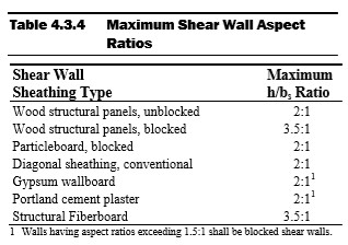
The Perforated Design Method assumes that all openings in the shear wall are able to transfer the loads from around the opening to full-length segments. This means that the full length of the wall, including segments with openings, can be included in the lateral force resisting system. The aspect ratios in Table 4.3.4 above are applicable for the Perforated Design Method as well. See SDPWS (2015) Figure 4C below describing the height (h) – to – width (b) ratio and that definition of a wall segment. It may seem that any shear wall may be designed using the Perforated Design Method, as it allows shear wall segments above and below openings to be accounted in the capacity of the lateral force resisting system. However, the Perforated Design Method may not be used with walls with non-uniform top-of-wall and bottom-of-wall elevations, per SDPWS (2015). In addition, shear wall height may not exceed 20 feet. If a shear wall has non-uniform elevations and/or the height exceeds the limit described in SDPWS (2015) Section 4.3.5.3, more complex methods of analysis will be necessary.
A sample shear wall calculation is performed below, finding the shear capacity of a 12’ wall with three 6’ segments. The first segment is full height, the second has a 3’ window 6’ above grade, and the last segment is full height. See the figure below for clarification. The top plate, bottom plate, and studs are to be Southern Pine with a specific gravity of 0.55. OSB Sheathing is 7/16” and a 32/16 APA span is used. Studs are spaced 16” o.c. and the panels are fastened using 8d common nails. A distributed live load of 80 plf and a distributed dead load of 40 plf are acting downward on the system. In addition, a 8 plf uplift force is acting on the system and there is a concentrated shear at the top of 1,000 lbs. The wall weighs 1 psf and is constructed in a region where seismic does not govern. Panel edge fasteners are assumed to be spaced 6”.
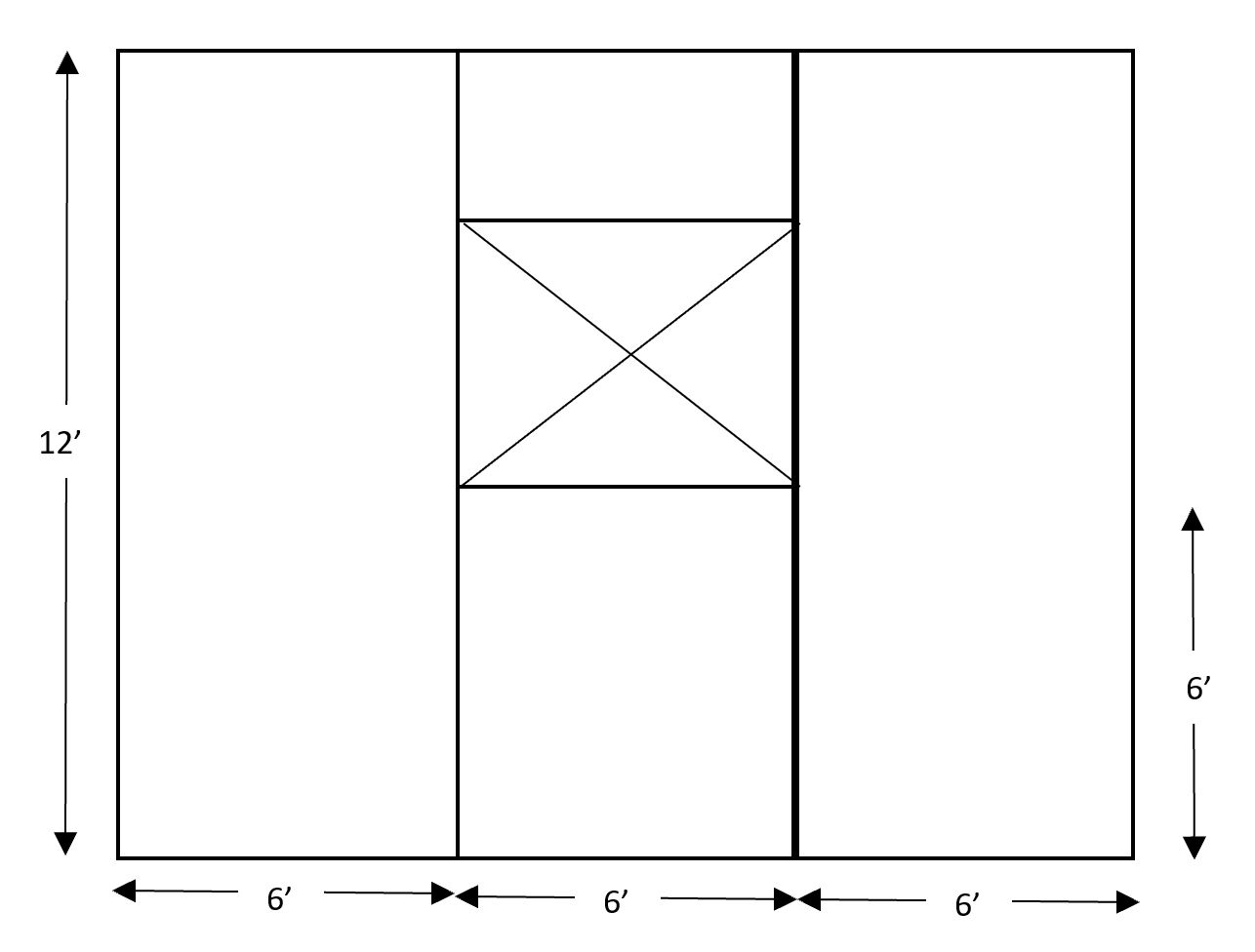
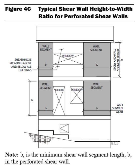
The example shown will start by solving the capacity of the wall using the Segmented Design Method. As stated, the Segmented Design Method does not consider any panels with openings, therefore, the middle segment cannot be considered.
The first step is the group the loads. The dead loads from the above the wall and the weight of the boards will be added to find total dead load the system must resist. To find the self-weight of the wall along the bottom of the plywood, the weight in psf is multiplied by the height in feet. This gives a self-weight of 12 plf. Added to the dead load above the wall, we have a total dead load along the bottom of the wall of 52 plf. The 52 plf dead load is added to the 80 plf live load to find a total downward force of 132 plf. The shear in the collectors throughout the wall is equivalent to the shear at the top of the wall (1,000 lbs) divided by the total length of the segments resisting the shear. Because the middle segment is not resisting the shear, the length of the wall is taken as 12’. The collector is experiencing 83.33 lb/ft of shear. This is also known as the unit shear, or Vm .
Next, the shear capacity of the plates and studs are considered. Using Table 4.3A from AWC’s SDPWS (2015), the nominal unit shear, vw, is 365 plf. A 2.0 multiplier is used per SDPWS (2015) 4.3.3. Per footnote 3 of Table 4.3A, a specific gravity multiplier is not necessary. A final unit shear capacity for the system is 730 lb/ft for the plates and studs.
The total shear wall capacity is taken as the 730 lb/ft multiplied by the length of the wall resisting the load, 12’. The total shear wall capacity is 8,760 lb. The wall is able to resist the full applied shear of 1,000 lbs.
The same calculations can be performed using the Perforated Design Method. The difference here is found in the unit shear calculation. Unlike the Segmented Design Method, the Perforated Design Method considers a few more adjustments. The Perforated Design Method takes in account the Maximum Opening Height Ratio (MOHR). This is taken as the height of the opening. In this example, the bottom of our 3’ window is 6’ above grade, resulting in a MOHR of 9’. The Maximum Opening and Wall Height Ratio is then considered as the maximum height of the opening divided by the height of the wall. 9’ divided by 12’ results in a 0.75 maximum opening and wall height ratio. The last adjustment needed is the Shear Capacity Adjustment Factor, Co, described in SDPWS (2015) Equation 4.3-5. To calculate Co, the Sheathing Area Ratio, r, needs to be calculated using SDPWS (2015) equation 4.3-6. The calculation of Co and r is below.
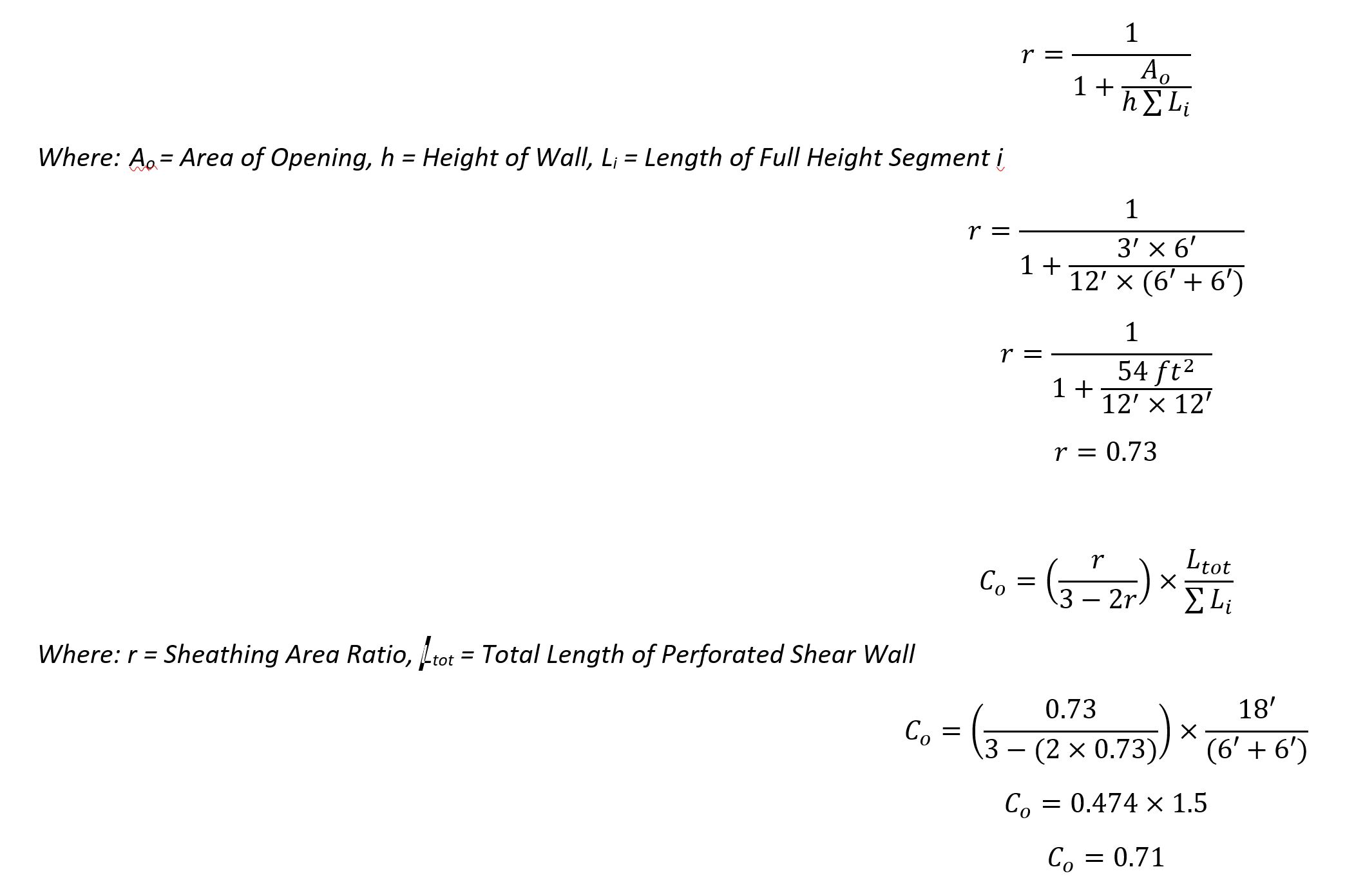
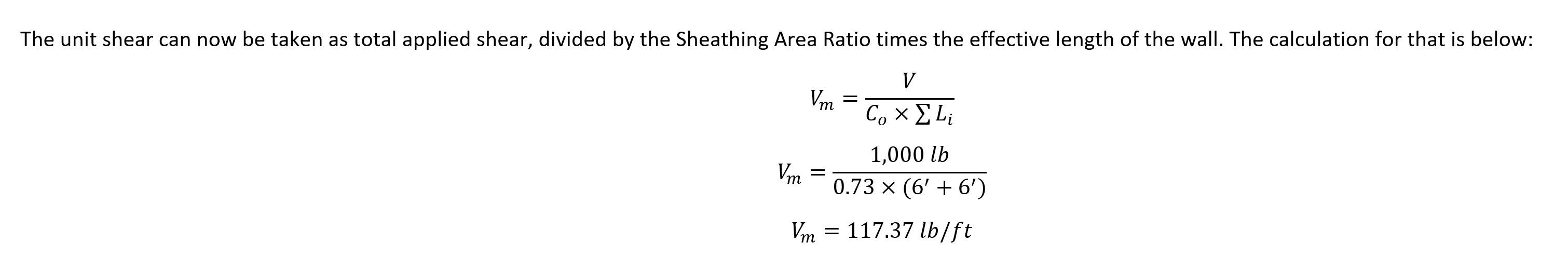
Using the Perforated Design Method, we found that the unit shear along the top and bottom of the shear wall is greater due to the opening in the wall. This means that a greater number of anchors would be needed around the edges of the system to account for the greater unit shear.
Engineering Express offers their clients a state-of-the-art calculator to calculate the needed anchors in a shear wall. The calculator uses empirical data and equations specified in codes and standards to determine the capacity of the shear wall itself and the anchors for shear walls of varying materials and sizes with up to 5 openings.
Calculation results can be reviewed and certified by a Professional Engineer for permit from Engineering Express. Click here to try the calculator out at no charge or obligation.
Contact Us to discuss your job specific or calculator need.
Article by Alexis Boden, EI, Project Designer, Engineering Express
Tell us how can we improve this post?
Starter List in Evaluating Your Building Component For Product Approvals & TER’s
The Ultimate Starter Checklist for Evaluating Your Building Component
Before a product can be approved, installed, or even marketed, it must prove compliance with building code performance standards.
Whether you’re developing a rooftop mechanical unit, sunroom system, or custom enclosure, success depends on one thing:
How well you prepare your submission.
CHECKLIST
Product Documentation
A complete technical package allows your engineer to understand your product immediately. Include:
-
Dimensioned drawings showing all key components, fasteners, and materials -
Assembly and section views (connection details, panel spacing, joint types) -
Weights and sizes for all models under evaluation -
Material specifications for each structural part (steel, aluminum, etc.) -
CAD / SolidWorks files for clarity (mechanical internals optional)
A complete technical package allows your engineer to understand your product immediately. Include:
-
Dimensioned drawings showing all key components, fasteners, and materials -
Assembly and section views (connection details, panel spacing, joint types) -
Weights and sizes for all models under evaluation -
Material specifications for each structural part (steel, aluminum, etc.) -
CAD / SolidWorks files for clarity (mechanical internals optional)
Performance Targets
Don’t leave your engineer guessing. Clearly outline:
-
Target design pressure or installed height -
Applicable building code version (e.g., FBC 2023, ASCE 7-16) -
Expected service conditions (indoor/outdoor, exposure) -
Whether you’ll allow reinforcement or design adjustments if needed
Don’t leave your engineer guessing. Clearly outline:
-
Target design pressure or installed height -
Applicable building code version (e.g., FBC 2023, ASCE 7-16) -
Expected service conditions (indoor/outdoor, exposure) -
Whether you’ll allow reinforcement or design adjustments if needed
Wind & Structural Loading
For wind- or structure-sensitive products:
-
Identify installation location (rooftop or ground-mounted) -
Define exposure category (C or D) -
Provide design wind speed, height above grade, and site elevation -
Note any obstructions or shielding nearby
For wind- or structure-sensitive products:
-
Identify installation location (rooftop or ground-mounted) -
Define exposure category (C or D) -
Provide design wind speed, height above grade, and site elevation -
Note any obstructions or shielding nearby
Anchorage & Connection Details
Connections are often the critical point in any design. Provide:
-
Anchor type, size, and spacing -
Substrate information (concrete, steel, aluminum, deck type) -
Frame and base-pan details with restraint locations -
Material strengths for both product and support structures
Connections are often the critical point in any design. Provide:
-
Anchor type, size, and spacing -
Substrate information (concrete, steel, aluminum, deck type) -
Frame and base-pan details with restraint locations -
Material strengths for both product and support structures
Reporting the Results
A professional evaluation should include:
-
Maximum allowable design pressures (uplift, lateral) -
Installation limitations (sizes, anchor spacing, configuration) -
Clear, permit-ready installation guidance
A professional evaluation should include:
-
Maximum allowable design pressures (uplift, lateral) -
Installation limitations (sizes, anchor spacing, configuration) -
Clear, permit-ready installation guidance
Typical Products We Evaluate
This checklist applies to a wide range of systems, such as:
-
Rooftop mechanical units and HVAC enclosures -
Sunrooms, patio covers, and screen systems -
Windows, doors, and curtainwall assemblies -
Solar racks, tanks, towers, signs, and canopies -
Custom fabricated or composite structures
If it resists wind, anchors to a building, or carries load, it qualifies.
Engineering success begins with clarity and preparation.
A well-documented submission saves time, reduces costs, and builds confidence with reviewers and clients alike.
When you partner with Engineering Express, you gain a team that understands both the code and the process — helping you move from concept to certified approval efficiently and professionally.
USEFUL ARTICLES
For guidance with your next project, explore our Plans, Calculators, Knowledge Base,
or contact us directly for site-specific support
Visit Our Plan Store
Online Design Calculators
Visit Our Knowledge Base
Site specific project request
Chat with a Designer
Chat with a Designer
Site specific project request
Visit Our Plan Store
Online Design Calculators
Tell us how can we improve this post?
Flood Engineering Glossary
FLOOD GLOSSARY
The following is provided as a curated summary of terms taken from the referenced standards that appear in the article footing.
SEE ALSO OUR GENERAL GLOSSARY OF TERMS
NATIONAL FLOOD INSURANCE PROGRAM (NFIP)
The Federal program, create by an act of Congress in 1968, that makes flood insurance available in communities that enact satisfactory floodplain management regulations.
FLOOD INSURANCE RATE MAP (FIRM)
The official map of a community prepared by FEMA that shows the BFE, along with the special flood hazard area and the risk premium zones for flood insurance purposes. Once it has been accepted, the community is part of the regular phase of the NFIP.
FIRM MAP LINK
https://msc.fema.gov/portal/search
NATIONAL GEODETIC VERTICAL DATUM OF 1929 (NGVD)
Elevation datum plane previously used by FEMA for the determination of flood elevations.
NORTH AMERICAN VERTICAL DATUM OF 1988 PLANE (NAVD)
Elevation datum currently used by FEMA for the determination of flood elevations.
FEMA FLOOD ZONES
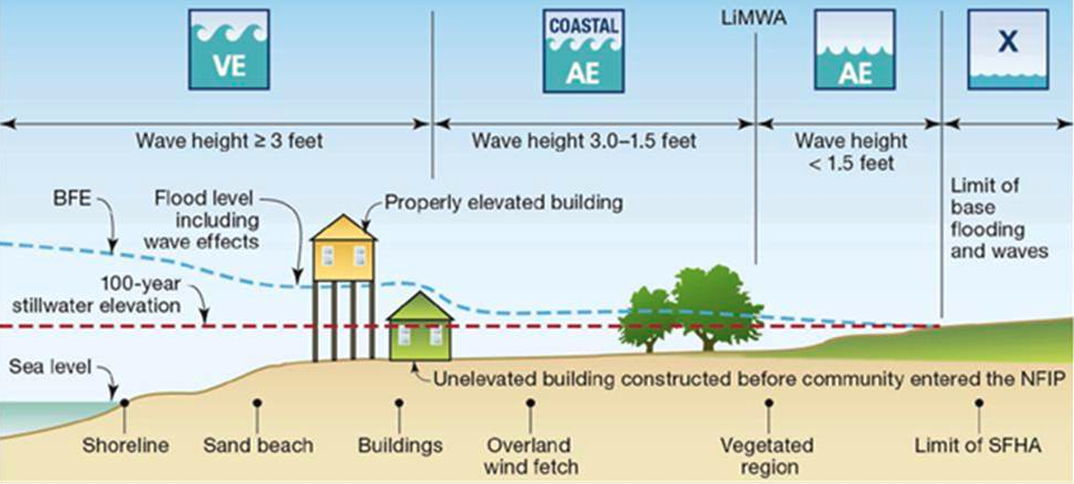
FEMA Flood Insurance Rate Map (coastal)
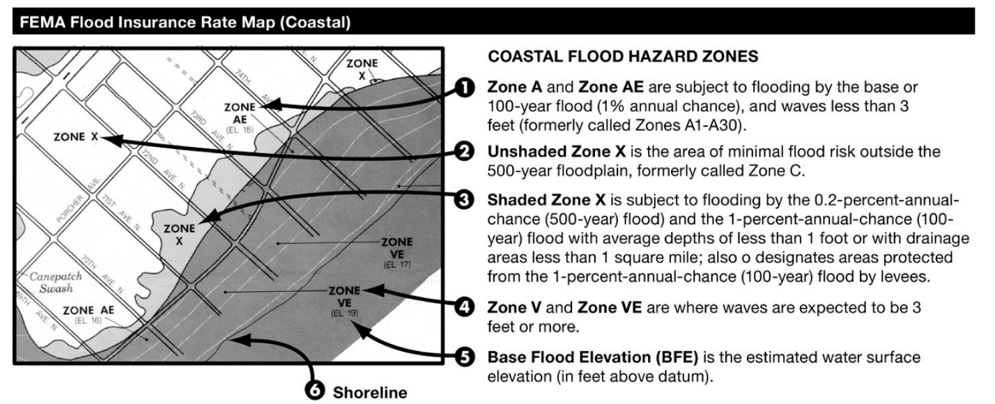
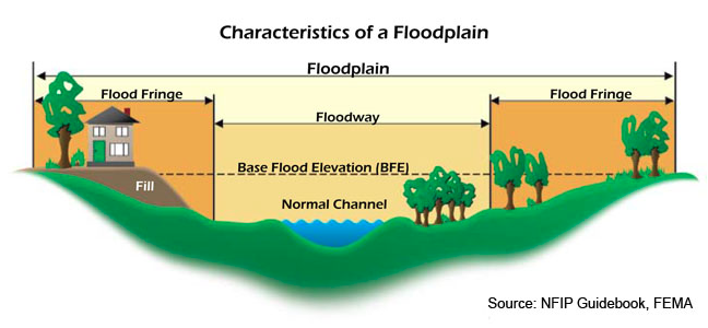
ASCE – Most Restrictive Zone Applies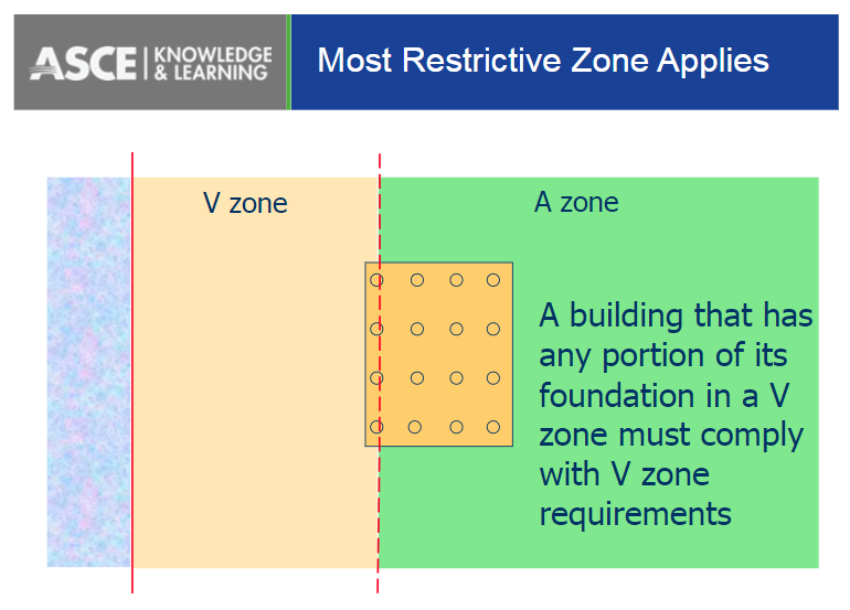
Flood hazard areas identified on the Flood Insurance Rate Map are identified as a Special Flood Hazard Area (SFHA). SFHA are defined as the area that will be inundated by the flood event having a 1-percent chance of being equaled or exceeded in any given year. The 1-percent annual chance flood is also referred to as the base flood or 100-year flood. SFHAs are labeled as Zone A, Zone AO, Zone AH, Zones A1-A30, Zone AE, Zone A99, Zone AR, Zone AR/AE, Zone AR/AO, Zone AR/A1-A30, Zone AR/A, Zone V, Zone VE, and Zones V1-V30. Moderate flood hazard areas, labeled Zone B or Zone X (shaded) are also shown on the FIRM, and are the areas between the limits of the base flood and the 0.2-percent-annual-chance (or 500-year) flood. The areas of minimal flood hazard, which are the areas outside the SFHA and higher than the elevation of the 0.2-percent-annual-chance flood, are labeled Zone C or Zone X (unshaded).
100-YEAR FLOOD
The flood that has a one-percent chance of being equaled or exceeded in any given year. It is also known as the Base Flood.
SPECIAL FLOOD HAZARD AREAS (SFHA)
Portion of the floodplain subject to inundation by the base flood, designated Zone A, AE, A1 – A30, AH, AO, AR, V, VE, or V1 – V30 on a FIRM.
V ZONES (COASTAL HIGH HAZARD)
Area within a special flood hazard area extending from offshore to the inland limit of a primary frontal dune along an open coast and any other area that is subject to high velocity wave action from storms or seismic sources. This area is designated on FIRMs as velocity zones V, VO, VE, or V1-30.
COASTAL A ZONES (CAZ)
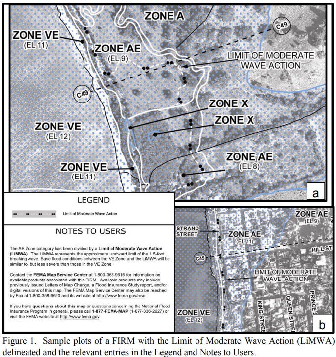
Area within a special flood hazard area, landward of a V Zone or landward of an open coast without mapped V Zones. In a Coastal A Zone, the principal source of flooding must be astronomical tides, storm surges, seiches, or tsunamis, not riverine flooding. During the base flood conditions, the potential for breaking wave heights shall be greater than or equal to 1.5 ft. The inland limit of the Coastal A Zone is (1) the Limit of Moderate Wave Action if delineated on a FIRM, or (2) designated by the authority having jurisdiction.
LIMIT OF MODERATE WAVE ACTION (LiMWA)
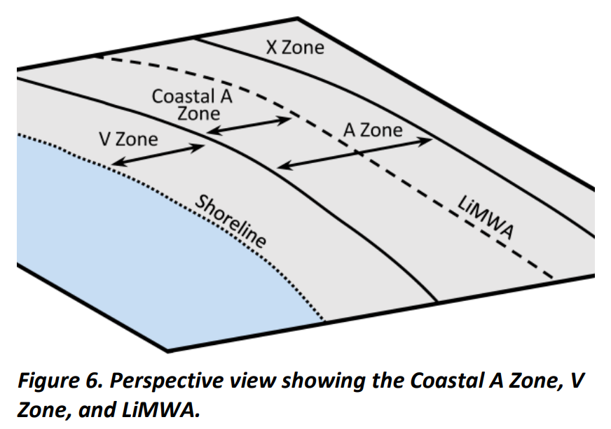
Line shown on FIRMs to indicate the inland limit of the 1.5-ft breaking wave height during the base flood.
A ZONES
Areas subject to inundation by the 1-percent-annual-chance flood event generally determined using approximate methodologies. Because detailed hydraulic analyses have not been performed, no Base Flood Elevations (BFEs) or flood depths are shown. Mandatory flood insurance purchase requirements and floodplain management standards apply.
X OR C ZONE
The areas of minimal flood hazard, which are the areas outside the SFHA and higher than the elevation of the 0.2-percent-annual-chance flood, are labeled Zone C or Zone X (unshaded).
BASE FLOOD ELEVATION (BFE)
Elevation of the 100-year flood. The BFE is determined by statistical analysis for each local area and is designated on the FIRMs. This elevation is the basis of the insurance and floodplain management requirements of the NFIP.
DESIGN FLOOD ELEVATION (DFE)
The elevation of the highest flood (generally the BFE including freeboard) that a retrofitting method is designed to protect against. Also referred to as Flood Protection Elevation.
FREEBOARD (FB)
Additional amount of height incorporated into the DFE to account for uncertainties in the determination of flood elevations.
FINISHED FLOOR (FF)
Finished floor elevation above a referenced datum typically sea level.
DESIGN WATER VELOCITY
Speed at which water moves during a flood. Velocities usually vary across the floodplain. They are usually greatest near the channel and lowest near the edges of the floodplain.
HYDROSTATIC LOADS
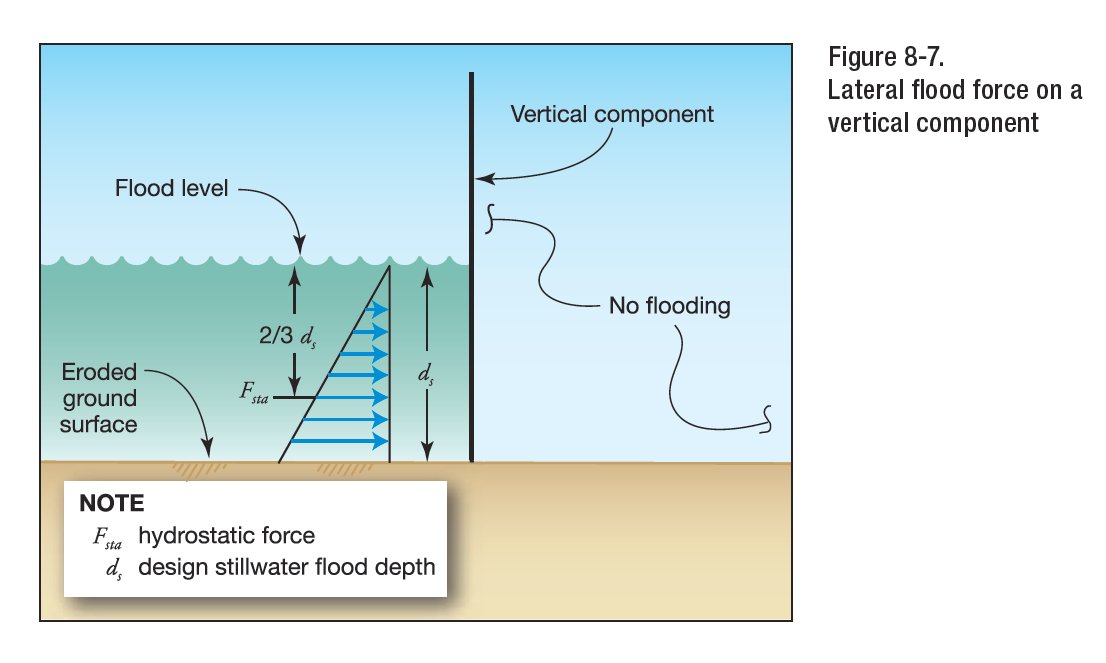
Hydrostatic loads are those caused by water either above or below the ground surface, free or
confined, which is either stagnant or moves at velocities less than 5 ft/s (1.52 m/s). These loads are equal to the product of the water pressure multiplied by the surface area on which the pressure acts. Hydrostatic pressure at any point is equal in all directions and always acts perpendicular to the surface on which it is applied. Hydrostatic loads can be subdivided into vertical downward loads, lateral loads, and vertical upward loads (uplift or buoyancy). Hydrostatic loads acting on inclined, rounded, or irregular surfaces may be resolved into vertical downward or upward loads and lateral loads based on the geometry of the surfaces and the distribution of hydrostatic pressure.
HYDRODYNAMIC LOADS

Where water velocities do not exceed 10 ft/s (3.05 m/s), dynamic effects of moving water shall be permitted to be converted into equivalent hydrostatic loads by increasing the DFE for design purposes by an equivalent surcharge depth, dh, on the headwater side and above the ground level only. Hydrodynamic loads are those loads induced by the flow of water moving at moderate to high velocity above the ground level. They are usually lateral loads caused by the impact of the moving mass of water and the drag forces as the water flows around the obstruction.
SURCHARGE DEPTH
When dynamic effects are converted to equivalent hydrostatic loads, the equivalent surcharge depth shall be added to the DFE design depth and the resultant hydrostatic pressures applied to, and uniformly distributed across, the vertical projected area of the building or structure that is perpendicular to the flow. Surfaces parallel to the flow or surfaces wetted by the tail water shall be subject to the hydrostatic pressures for depths to the DFE only.
BREAKING WAVE PRESSURE

Maximum combined dynamic and static wave pressures, also referred to as shock pressures in lb/ft^2 (kN/m^2).
BREAKING WAVE FORCE
Net breaking wave force per unit length of structure, also referred to as shock, impulse, or wave impact force in lb/ft (kN/m), acting near the still water elevation.
BREAKING WAVE HEIGHT
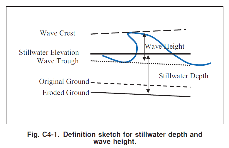
Vertical distance between wave crest and wave trough.
STILLWATER DEPTH
Elevation that the surface of the water would assume in the absence of waves referenced to a datum.
DEBRIS IMPACT FORCE

Debris Impact Load Per FEMA P-55
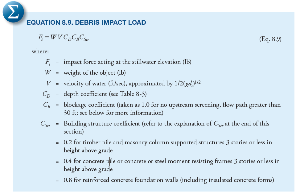
Debris impact loads are imposed on a building by objects carried by moving water. The magnitude of these loads is very difficult to predict, but some reasonable allowance must be made for them. The loads are influenced by where the building is located in the potential debris stream, specifically if it is:
- Immediately adjacent to or downstream from another building
- Downstream from large floatable objects (e.g., exposed or minimally covered storage tanks)
- Among closely spaced buildings
DEBRIS CHARACTERISTICS
The size, shape, and weight of waterborne debris may vary according to region. For example, the coasts of Washington, Oregon, and other areas may be subject to very large debris in the form of whole trees and logs along the shoreline. The southeastern coast of the United States may be more subject to debris impact from dune crossovers and destroyed buildings than other areas. In the absence of information about the nature of potential debris, a weight of 1,000 pounds is recommended as the value of W. Objects with this weight could include portions of damaged buildings, utility poles, portions of previously embedded piles, and empty storage tanks.
DEPTH COEFFICIENT (CD)
Per FEMA P-55
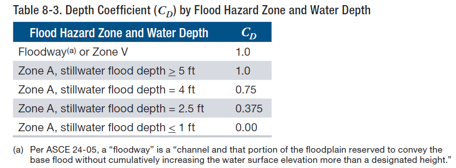
The depth coefficient (CD) accounts for reduced debris velocity as water depth decreases. For buildings in Zone A with stillwater flood depths greater than 5 feet or for buildings in Zone V, the depth coefficient = 1.0.
UPSTREAM SCREENING/BLOCKAGE COEFFICIENT (CB)
Per FEMA P-55
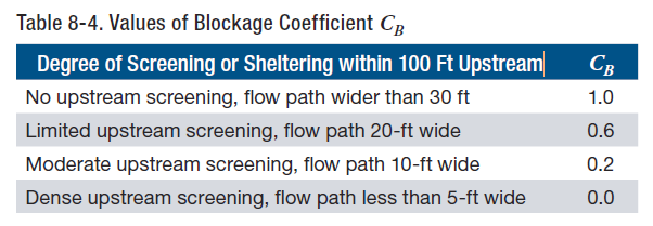
The blockage coefficient (CB) is used to account for the reduction in debris velocity expected to occur because of the screening provided by trees and other structures upstream from the structure or building on which the impact load is being calculated.
BUILDING STRUCTURE COEFFICIENT (CSTR)
Stiff or rigid buildings and structures with natural periods similar to the impact duration will see an amplification of the impact load. More flexible buildings and structures with natural periods greater than approximately four times the impact duration will see a reduction of the impact load. Likewise, stiff or rigid components will see an amplification of the impact load; more flexible components will see a reduction of the impact load. Calculating the natural period can be carried out using established methods that take building mass, stiffness, and configuration into account. Coefficient values for Cstr, (0.2, 0.4, and 0.8) were generated by selecting input values recommended in ASCE 7-10, Chapter C5, with appropriate assumptions made to model typical coastal residential structures.
Article provided by Zachary A. Rubin, P.E.
Engineering Express is glad to discuss your question or need in this field.
Feel free to Contact Us or call us at the numbers listed below.
RELATED ARTICLES:
Also see: FLOOD RESISTANT DESIGN & FLOODPROOFING OF BUILDINGS
REFERENCES & SOURCES:
- FEMA 3-93: Non-Residential Floodproofing for Buildings Located in Special Flood Hazard Areas in Accordance with National Flood Insurance Program
- FEMA P-55: Coastal Construction Manual
- FEMA 102: Floodproofing for Non-Residential Structures
- FEMA 259: Engineering Principles and Practices of Retrofitting Floodprone Residential Structures
- FEMA FL-RA1: Dry Floodproofing Operational Considerations
- gov
- ASCE 24-14: Flood Resistant Design
- ASCE 7-10: Minimum Design Loads for Buildings and Other Structures
Tell us how can we improve this post?
Flood Resistant Design & Floodproofing of Buildings
An engineer’s walk through of the design requirements for flood resistant design of building components
With Engineering Express’s early start with floodproofing designs for floor barriers and exterior glazing in projects across the US, we quickly became experts in this field. We’ve witnessed and directed static and dynamic flood testing, sat on industry meetings, met with industry officials, and designed and calculated flood barriers of all kinds across the US, most notably for public train and transit systems in NY and NJ.
We asked one of our senior flood engineers Zach Rubin, PE to summarize the conditions and design parameters for flood in this knowledge base article. Links to references appear at the bottom of the article.
FIRST A WORD ABOUT FEMA
Federal Emergency Management Agency (FEMA) is an independent agency created in 1978 to provide a single point of accountability for all Federal activities related to disaster mitigation and emergency preparedness, response, and recovery. FEMA administers the National Flood Insurance Program (NFIP). The NFIP is the Federal Program, created by an act of Congress in 1968, that makes flood insurance available in communities that enact satisfactory floodplain management regulations. The Base Flood Elevation (BFE), based on site location, is available via the Flood Insurance Rate Map (FIRM). The FIRM is an official map of a community prepared by FEMA that shows the BFE, along with the special flood hazard area and the risk premium zones for flood insurance purposed. Once it has been accepted, the community is part of the regular phase of the NFIP. The FIRM Map can be viewed by the following the link FIRM MAP LINK: https://msc.fema.gov/portal/search
FLOOD PROOFING CERTIFICATE
Documentation of certification by a registered professional engineer or architect that the design and methods of construction of a non-residential building are in accordance with accepted practices for meeting the floodproofing requirements in the community’s floodplain management ordinance. This documentation is required for both floodplain management requirements and insurance rating purposes.
For insurance rating purposes, a building’s floodproofed design elevation must be at least one foot above the BFE to receive full rating credit for the floodproofing. If the building is floodproofed only to the BFE, the flood insurance rates will be considerably higher.
Communities are encouraged to use the one-page FEMA floodproofing certification form because it fulfills NFIP insurance rating needs as well as floodplain management requirements.
DRY FLOODPROOFING
Dry floodproofing is a combination of measures that results in a structure, including the attendant utilizes and equipment being watertight with all elements substantially impermeable and with structural components having the capacity to resist flood loads. The intention of dry floodproofing is keep the water completely out of the structure examples include permanent or removable flood shields to protect doors/windows/sewer lines, watertight impervious membrane sealant systems, impermeable sheeting and sheathing, and reinforcement of walls to withstand flood loading. There are limitations where dry floodproofing can be utilized which are outlined in FEMA 3-93 and ASCE 24.
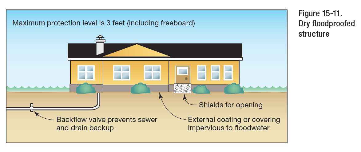
FEMA 3-93 Figure 15-11 Dry Floofproofed Structure
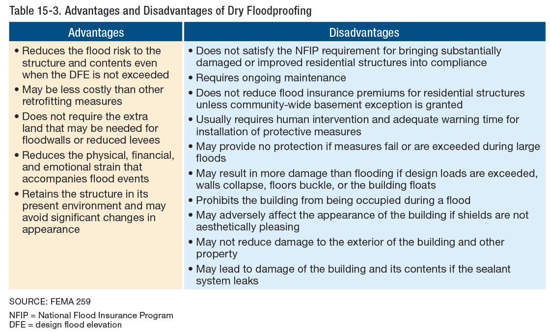
FEMA P-55
FLOOD EMERGENCY OPERATIONS PLAN
As dry floodproofing systems require human intervention to deploy the physical barrier, both ASCE 24 and the NFIP guidelines require that the operations, maintenance, and testing plan of a dry floodproofing system be developed during the design of the system and regularly updated throughout the life of the building. FEMA recommends that the operations, maintenance, and testing plan include the following items:
- A decision tree identifying responsible parties, a sequence and timeline by which various components will be installed, including identified triggers or benchmarks to initiate procedures.
- A list of personnel, equipment, and supplies needed to deploy all system components
- A map of the equipment storage location and component deployment locations
- A record of the manufacturer or designer and their contact information for expediting replacement parts and support as needed
- A copy of the NFIP Floodproofing Certificate
WET FLOODPROOFING
Wet floodproofing is a floodproofing method that relies on the use of flood damage-resistant materials and construction techniques in uninhabited areas of a structure that are below the elevation required by intentionally allowing those areas to flood. Wet floodproofing is often used for structures with basements and crawlspaces when other mitigation techniques are technically infeasible or too costly. Effective wet floodproofing entails that the floodwaters enter and exit the structure in such a way that damage to the structure and its contents are minimized examples include flood vents, breakaway walls, and flood damage resistant building materials. There are limitations where wet floodproofing can be utilized which are outlined in FEMA 3-93 and ASCE 24.

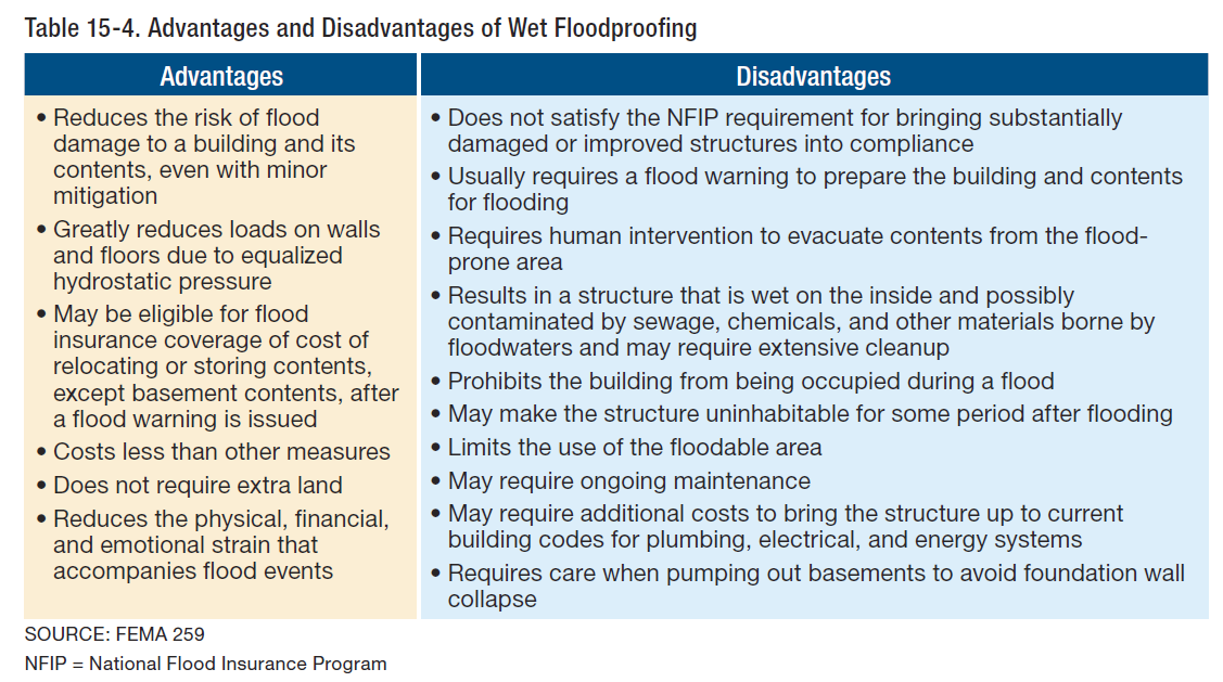
ALLOWABLE SEEPAGE RATES FOR NON-RESIDENTIAL STRUCTURES
Per FEMA 102, acceptable seepage rates should not exceed an amount which would result in accumulation of more than four (4) inches of water depth during a 24-hour period, if there were no devices provided for its removal. However, sump pumps would be required to control such seepage.
FLOOD DESIGN
FREEBOARD
Under the NFIP, freeboard is a factor of safety, usually expressed in feet above a flood level, for the purposes of floodplain management. Freeboard is intended to compensate for the many unknown factors that could contribute to flood heights greater than the heights calculated for a selected size flood and floodway conditions, such as the hydrological effect of urbanization of the watershed. Freeboard is additional height incorporated into the Design Flood Elevation (DFE), and may be required by State or local regulations or be desired by a property owner.
DESIGN FLOOD ELEVATION
The DFE is the elevation of the design flood, or the flood protection elevation required by a community, including wave effects, relative to the National Geodetic Vertical Datum (NGVD), North American Vertical Datum (NAVD), or other datum. The DFE is the locally adopted regulatory flood elevation. If a community regulates to minimum NFIP requirements, the DFE is identical to the BFE. If a community chooses to exceed minimum NFIP requirements, the DFE exceeds the BFE.
HYDROSTATIC LOADS

Hydrostatic Loads Explained Per FEMA P-55
Hydrostatic loads caused by a depth of water to the level of the DFE shall be applied over all surfaces involved, both above and below ground level, except that for surfaces exposed to free water, the design depth shall be increased by 1 ft (0.30 m). Hydrostatic loads are those caused by water either above or below the ground surface, free or confined, which is either stagnant or moves at velocities less than 5 ft/s (1.52 m/s). These loads are equal to the product of the water pressure multiplied by the surface area on which the pressure acts.
HYDRODYNAMIC LOADS (NON-BREAKING AND BROKEN WAVES)
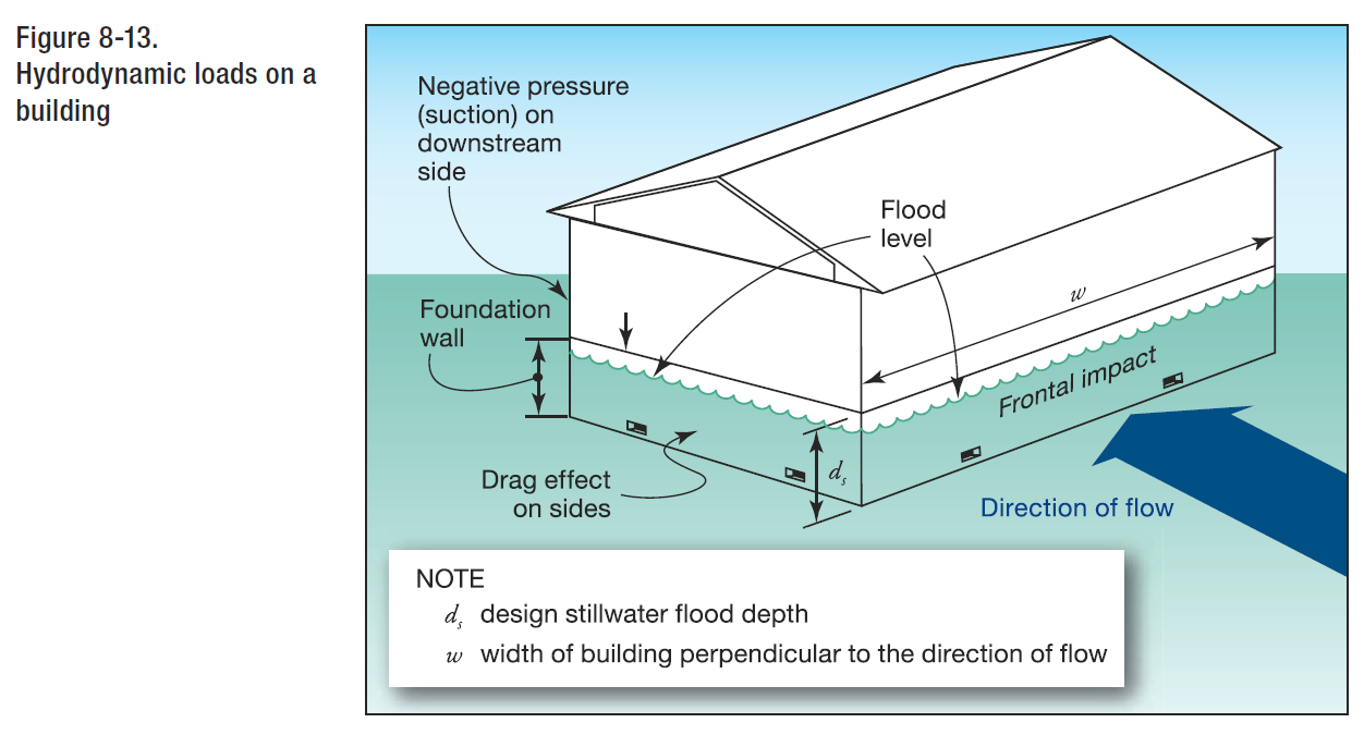
FEMA P-55
Dynamic effects of moving water shall be determined by a detailed analysis utilizing basic concepts of fluid mechanics. Where water velocities do not exceed 10 ft/s (3.05 m/s), dynamic effects of moving water shall be permitted to be converted into equivalent hydrostatic loads by increasing the DFE for design purposes by an equivalent surcharge depth, dh, on the headwater side and above the ground level only. The equivalent surcharge depth shall be added to the DFE design depth and the resultant hydrostatic pressures applied to, and uniformly distributed across, the vertical projected area of the building or structure that is perpendicular to the flow. Surfaces parallel to the flow or surfaces wetted by the tail water shall be subject to the hydrostatic pressures for depths to the DFE only. Hydrodynamic loads are those loads induced by the flow of water moving at moderate to high velocity above the ground level. They are usually lateral loads caused by the impact of the moving mass of water and the drag forces as the water flows around the obstruction.
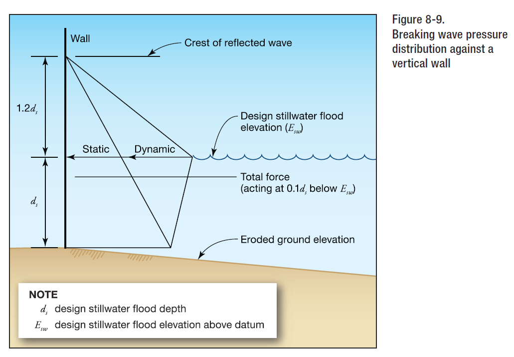
Wave loads shall be determined by one of the following three methods: (1) by using analytical procedures, (2) by more advanced numerical modeling procedures, or (3) by laboratory test procedures (physical modeling). Wave loads are those loads that result from water waves propagating over the water surface and striking a building or other structure. Design and construction of buildings and other structures subject to wave loads shall account for the following loads: waves breaking on any portion of the building or structure; uplift forces caused by shoaling waves beneath a building or structure, or portion thereof; wave runup striking any portion of the building or structure; wave-induced drag and inertia forces; and wave-induced scour at the base of a building or structure, or its foundation. The magnitude of wave forces (lb/ft2) (kN/m2) acting against buildings or other structures can be 10 or more times higher than wind forces and other forces under design conditions. Thus, it should be readily apparent that elevating above the wave crest elevation is crucial to the survival of buildings and other structures.
DEBRIS IMPACT
From FEMA P-55 Figure 2-8
Impact loads are those that result from debris, ice, and any object transported by floodwaters striking against buildings and structures, or parts thereof. Impact loads shall be determined using a rational approach as concentrated loads acting horizontally at the most critical location at or below the DFE. Impact loads are those that result from logs, ice floes, and other objects striking buildings, structures, or parts thereof. U.S. Army Corps of Engineers (1995) divides impact loads into three categories: (1) normal impact loads, which result from the isolated impacts of normally encountered objects, (2) special impact loads, which result from large objects, such as broken up ice floats and accumulations of debris, either striking or resting against a building, structure, or parts thereof, and (3) extreme impact loads, which result from very large objects, such as boats, barges, or collapsed buildings, striking the building, structure, or component under consideration. A 1,000 lb object can be considered a reasonable average for flood-borne debris. Design for extreme impact loads is not practical for most buildings and structures.
FLOOD COMBINATIONS
There is no guidance regarding combinations of flood loads therefore it is at the discretion of the engineer to determine how to combine flood loads based upon the site conditions and project exposure. Based on our engineering judgement, we feel flood loading should be combined as follows:
- Apply hydrostatic and hydrodynamic concurrently
- Apply hydrostatic/hydrodynamic with debris impact
- Apply hydrostatic with breaking wave impact
LACK OF FLOOD DESIGN PROVISIONS
There are discrepancies and lack of provisions among the resources referenced herein regarding how to combine flood loads and which methodology to use among the varied sources. Ultimately, the engineer needs to evaluate the different applicable loading scenarios, published formulae, and project liability, then decide what level of service is most appropriate given the structure criticality and functionality.
SUMMARY
Engineering Express has designed dozens of static and hydrodymamic designs for flood systems of glass, metal, and fabric materials, directed and witnessed testing, and performed complex calculations to prove design for scrutinizing reviewers. We’ve also met with companies such as FM Global at their Cleveland Offices and they’ve visited with us, and work frequently with Brizaga Inc (information below) to tap into the fast developing field of flood design. Few know and understand the rules which are being rewritten and clarified at a lightning fast pace.
Engineering Express is glad to discuss your question or need in this field.
Feel free to Contact Us or call us at the numbers listed below.
Article provided by Zachary A. Rubin, P.E.
RELATED ARTICLES:
REFERENCES & SOURCES:
- FEMA 3-93: Non-Residential Floodproofing for Buildings Located in Special Flood Hazard Areas in Accordance with National Flood Insurance Program
- FEMA P-55: Coastal Construction Manual
- FEMA 102: Floodproofing for Non-Residential Structures
- FEMA 259: Engineering Principles and Practices of Retrofitting Flood-Prone Residential Structures
- FEMA FL-RA1: Dry Floodproofing Operational Considerations
- gov
- ASCE 24-14: Flood Resistant Design
- ASCE 7-10: Minimum Design Loads for Buildings and Other Structures
- FM2510: American Standard for Flood Mitigation Equipment
Michael A. Antinelli, PE, CFM Co-Founder BRIZAGA, Inc. 100 SE 3rd Ave, Suite 1000, Fort Lauderdale, FL 33394 P (954) 834-3533 C (954) 520-2384 E [email protected]
Tell us how can we improve this post?
Wind Speed vs. Wind Pressure Explained
Many don’t understand how wind works & state that a product is rated to a specific wind speed. This is false advertising & not true.
There’s no such thing as “Rated to XXX MPH wind”
This is frequently seen in marketing materials which is a false & misleading statement
that comes with many unwritten disclaimers.
The Why
The formula that converts wind velocity to wind pressure has many variables. Each variable affects the resulting pressure for a given wind velocity. A 100mph wind velocity for example can produce pressures as low as in the mid-teens (psf) to upwards of 50psf, even 60psf, and more*. These variables include such features as building height, location of the area on the building, the terrain around the building, whether the building is on or near a hill, slope of the roof, size of the area in consideration, and more.
There are even two types of wind speeds and pressures that complicate things further, Allowable stress design and Load Factored Design (click here to learn more) as well as different wind codes that govern (Some use ASCE 7-05, most use ASCE 7-10, and there’s now ASCE 7-16 with yet different conversion factors for some building surfaces for the same wind velocity). Engineers deal with a common denominator when designing structures (wind pressure) which sets a uniform standard anywhere (yes even on the moon) for a force that a product can resist.
How We can help
1) Engineering Express provides certified wind charts for permit for windows, doors, and garage doors. Click Here to browse our plan store
2) Engineering Express also provides a free online tool to convert wind velocity to wind pressure. Click Here to access it
* ASCE 7-16 Exposure D, 300 ft MRH, Zones 5 and 3 respectively, 10sqft tributary area, enclosed structure, flat terrain, Kd=0.85, Forces upwards of 70psf + possible for hilly terrain, partially enclosed, Kd=1.0, at sea level.
Tell us how can we improve this post?
TEK Sheet Metal Screws (SMS) – About – Sizes – Gauges
Tek® screws have become an essential tool in construction and manufacturing, valued for their self-drilling capabilities that simplify a variety of projects. These screws eliminate the need for pre-drilling, saving time and effort while ensuring strong, reliable connections. Ideal for applications like metal roofing and steel framing, Tek® screws deliver durable, high-performance results, making them the go-to solution for professionals.
In this article, we’ll take a closer look at what Tek® screws are, their design features, and why they’re so widely used. We’ll also compare different types of Tek® screws, including their sizes, head styles, and the best uses for each, so you can better understand how to choose the right one for your projects.

What Are Tek® Screws?
Tek® screws are a type of self-tapping fastener with a unique design that allows them to drill their own hole as they are driven into materials. The small carving at the end of their tip, known as a drill bit, enables these screws to cut through various materials without the need for pre-drilling, streamlining the fastening process. It’s important to note that “Tek® screws” refers specifically to a brand of self-drilling screws. While they are commonly used as a generic term in the construction industry, designers and contractors should specify “self-drilling screws” or “sheet metal screws” in general contexts to include other brands.
Tek® screws are primarily used for metal-to-metal applications, although there is a specialized version, the reamer Tek® screw, designed specifically for wood-to-metal applications. Contractors often use these screws for joining metal-to-metal and, in certain cases, wood-to-metal. There are different drill points available depending on the material thickness, with the Tek® 5 (sometimes called a “beambuster”) being one of the longest and most powerful options. These screws allow users to fasten materials together without pre-drilling, making them an essential tool for many construction and manufacturing projects.
Standard self-drilling screws, including Tek® screws, are not designed for typical metal-to-wood applications. The drill bit creates a hole that is nearly the same size as the screw’s threaded portion, which prevents the threads from tapping into the wood securely. However, some screws, especially those used in roofing applications, feature a tiny drill bit (usually a #1 drill bit). This smaller hole allows the threads to engage properly, providing a strong hold in both metal and wood materials.
Design Characteristics of Tek® Screws
Sizes and Head Styles
Tek® screws come in a wide range of sizes, from smaller #6 diameter screws to larger #12 diameter screws, providing flexibility for various applications. The size of the screw, as well as its head style, determines which type you need for your specific project. Common head styles include the hex washer head, ideal for heavy-duty metal installations, and the modified truss head, which offers a slightly rounded shape for different fastening needs. For flush surfaces, flathead screws are typically used.
Drive Types
The drive type is another important consideration. While many Tek® screws have a Phillips drive, square drive options are gaining popularity for better grip and torque control. For wood-to-metal applications, reamer Tek® screws, which feature wings near the drill bit, are designed to drill through multiple layers and securely fasten materials.
Bit Designs
The bit design of Tek® screws is another critical feature that varies depending on the application. The self-drilling tip is a defining characteristic of Tek® screws, allowing them to drill their own hole as they are driven in. The tips can vary in size and shape depending on the material being drilled. For example, screws used for light-duty metal might have a smaller, finer tip, while screws designed for heavy-duty applications like steel framing may have a larger, more aggressive tip. Reamer Tek® screws come with an additional set of wings that help cut through thicker materials, making them ideal for multi-layer applications.
Screw Materials
Tek® screws are available in various materials to suit different applications:
- – Zinc-Plated Steel: The most common type, offering very good rust resistance.
- – Weather-Guard Coated (STALGARD®): Protects ferrous metals from rust and corrosion better than many conventional finishes.
- – Stainless Steel: Available in both 18-8 and 410 grades. 18-8 provides excellent corrosion resistance and can be mildly magnetic, while 410 is stronger and magnetic, suitable for chemical environments.
- – Hybrid Screws: These feature a hard steel driver fused at mid-body with an 18-8 stainless steel head. The hard steel driver ensures superior drilling capability, while the 18-8 stainless steel head provides excellent corrosion resistance and durability.
- – Bi-Metal Tek® Screws: These screws combine a carbon steel tip for drilling into tough materials with a stainless steel body for durability and corrosion resistance. They are suitable for a wide range of fastening tasks, offering the necessary strength for challenging applications through varying tip designs, head styles, and sizes.
List of Fasteners
To help you choose the right tek screw for your project, we’ve put together a table that shows some common types of fasteners. You’ll find their key features and typical uses, making it easier to find the perfect match for your needs.
|
Special Purpose Fasteners
|
Head Styles
Screws come in various head styles, each designed for specific applications. Understanding these different types can help you choose the right screw for your project, ensuring better performance and a cleaner finish.
-
– Hex Washer Head (HWH): The built-in washer provides a stable bearing surface. These screws can be slotted or unslotted, with unslotted being more common. The length is measured from beneath the head.
-
– Pan Head: This low-profile head is available with either a Phillips or square drive. The length is measured from beneath the head.
-
– Flat Head: A countersunk head that sinks into wood for a flush finish. The length is measured from the top of the head.
-
– Oval Head: Similar to a flat head but with an oval-shaped top for a more finished appearance. The length is measured from the top of the head.
-
– Flat Head Reamer: A flat top with a Phillips drive, designed to ream wood and then cut steel in one step. The wings ream a clearance hole in thick, low-density materials to prevent thread engagement. When the point penetrates metal, the wings break off and the threads engage normally. The length is measured from the top of the head.
-
– Round Washer Head: Similar to a hex washer head but with a round head and a Phillips drive. Also known as Metal Lath, K-Lath, or Modified. The length is measured from beneath the head.
-
– Truss Screws: Known for attaching trusses and similar components. The length is measured from beneath the head.
-
– Wafer Head: Often called Plymetal screws, these are used to attach plywood to metal. The large wafer head sinks into the plywood and provides a large bearing surface. The length is measured from the top of the head.
-
– Drywall Bugle Head: Designed for fastening drywall to metal studs. The length is measured from the top of the head.
-
– Pan Framing: A Phillips drive screw used for attaching studs to tracks in framing. The length is measured from beneath the head.
-
– Pancake Head: A very low-profile head with a wide bearing surface, ideal for tight spaces. The length is measured from beneath the head.
-
– Square Trim: Features a square drive and a reduced head size, making it ideal for tight spaces. The length is measured from beneath the head.
Types of Sheet Metal Screws
Tapping screws, especially Type A, are referred to as “sheet metal screws” because one of their first applications was in ventilation ducts made of sheet metal. Over time, though, different types evolved. We’ll cover the common groups: thread forming, thread cutting, thread rolling and self drilling. The combination of point and thread style determines to which group the screw belongs.

Table showing the type designations for tapping and metallic screws. Source: Fastener Mart.
In screw designations, the letter “B” indicates spaced threads, as seen in Type AB or B screws. If the “B” is absent, like in Type F, the screw has machine screw threads. Two exceptions exist: Type A, though largely obsolete, still features spaced threads, and Type U metallic drive screws have spaced spiral threads.
Thread-forming screws are designed for use in thin, malleable materials. They have coarse threads and require a properly sized hole. As the screw is driven in, it enlarges the hole by pushing the material outward, often creating burrs. Common thread-forming screws include Types A and AB (standard point) and Type B (blunt point), typically used for sheet metal. Types A and AB are often interchangeable, and sizes range from #2 to 3/8.
For thicker, harder metals, thread-cutting screws are used. These screws have cutting flutes at the tip that act like a tap to create threads as they are driven in. Like taps, they require a correctly sized hole and produce chips. When installed in blind holes (holes that don’t go all the way through), chips accumulate at the bottom, so make sure there’s enough hole depth. In through-holes, chips exit through the other side. Be cautious of metal chips, as they can cause electrical shorts or contaminate lubricants. Type F is a common thread-cutting screw, and since it’s essentially a machine screw, its threads are more closely spaced than those of sheet metal screws. Once a hole is tapped by a thread-cutting screw, it can be replaced by a machine screw of the same size. Common sizes include 4-40 to 3/8-16.
Self-drilling screws, also called Teks®, feature a drill-like tip and spaced threads, similar to sheet metal screws. These screws drill, tap, and fasten in a single operation.
Type U metallic drive screws feature spaced spiral threads and a blunt point. They are forced under pressure into the material and are considered permanent fasteners, unlike other tapping screws that can be removed.
For low-density materials like plastic, particle board, Masonite®, and wood, High-Low thread screws are ideal. The “high” thread is sharp, while the “low” thread is about half the height. These screws reduce driving torque, minimize thread stripping, increase pull-out strength, and reduce the risk of cracking or splitting the material.
Finally, drywall screws are commonly used with sharp point and self-drilling styles. Sharp point screws are for wood and light gauge steel studs, while self-drilling screws are for heavy gauge steel studs. The bugle head design is self-countersinking, helping to resist tearing the drywall paper surface and preventing damage to the gypsum core.
Now that Tek® screws hold no secrets for you, we wish you the best of luck with your upcoming projects! If you have any questions about project design or need engineering assistance, simply click the button below to get in touch with us. Don’t forget to explore our other engineering articles for more valuable insights and tips!
For more detailed information and guidance on handling your future design projects, check out our online design calculators, contact us for site-specific projects, or reach out to us with your inquiries.
Online Design Calculators
Site specific engineering request
Chat with an engineer
Tell us how can we improve this post?
Designing Interior Glass? Here are some engineering code items to consider
Interior Glass: Not Just For Looks
When designing interior glass, you must consider both structural concerns and code requirements to ensure safety, functionality, and performance—
Here are some important code items and other concerns to consider:

Code References
Regarding differential horizontal movement:
From Both the IBC 2021 Section 2403.4 and FBC 2023 Section 2403.4, Interior Glazed Areas: Where interior glazing is installed adjacent to a walking surface, the differential deflection of two adjacent unsupported edges shall not be greater than the thickness of the panels when a force of 50 pounds per linear foot is applied horizontally to one panel at any point up to 42 inches above the walking surface.
Commentary: Think of this as ‘don’t get your fingers caught in the glass’… Someone leans against the glass, someone else puts their finger in the hole created, a person leans off the glass…
Regarding what evenly distributed load to put on the glass:
From IBC 2021 Section 1604.16 & FBC 2023 Section 1604.15, Interior Walls & Partitions: Interior walls and partitions that exceed 6 feet in height, including their finish materials, shall have adequate strength to resist the loads to which they are subjected but not less than a horizontal load of 5psf.
Commentary: Engineering Express prefers to design to 10psf due to other codes and standards outside the scope of this summary (such as ASCE-7), something to consider (also called the ‘shake test’). Anchorage, framing, glass strength per ASTM E1300 all need to be considered and designed to with this force applied to all portions of the glazed surface simultaneously.
Other Interior Glass Use Considerations
If the glass is to be used as a guardrail, all requirements of guardrails apply (see this article).
Fully tempered glass needs to be used where required by code in areas subject to impact (such are near doors, floors, stairwells, or as room dividers.
Safety glass must be permanently labeled with its standard of compliance. Safety glass is typically found in bathrooms and other areas where injury is an increased risk.
General Safety: Avoid unmarked clear glass in walkways—mark or use decorative/opaque film for visibility. Thermal & Environmental Performance: While less critical for interiors, thermal stresses from sunlight (for glass under skylights or highly sunlit zones) can cause thermal fracture. Use appropriate glazing as needed. Aesthetics & Functionality: Consider natural light, openness, and how the choice of glass supports your overall design intent without sacrificing privacy or safety.

In Closing
These are just some of the many code issues and items to address with interior glass design.
Always consult a licensed professional, even when installing interior glass to ensure the safety and wellbeing of the public and property you are designing for.
Contact us to help with your interior glass design or submit a request for quote for us to design your next interior glass project.
Tell us how can we improve this post?
Case Study: Phantom Screens – Is a Florida Product Approval Required?
![]() Product Approvals for building components are the general rule in Florida. Building officials, architects, insurance companies, even homeowners ask for them all the time, frequently refusing permits, insurance discounts, and product installations. So what is the legal ruling on when and if product approvals are required for this product?
Product Approvals for building components are the general rule in Florida. Building officials, architects, insurance companies, even homeowners ask for them all the time, frequently refusing permits, insurance discounts, and product installations. So what is the legal ruling on when and if product approvals are required for this product?
The Florida Building Code requires only certain products be tested and evaluated by an engineer, architect or approved test agency. Those evaluations or certified test documents can either be registered with the state of Florida through their statewide product approval system website or by use of a ‘Local Product Approval‘. There are only a few product types that require this type of approval per the Florida website (The state originally explained it in this presentation):
> Panel Walls
> Exterior Doors
> Roofing Products
> Skylights
> Windows
> Shutters
> Structural components
Ref: FAC 61G20-3.001
Outside of those products, a Statewide Florida Product Approval is optional and in many cases, isn’t even applicable for approval at the state level.
Miami Dade NOA’s (meaning Notices Of Acceptance), contrary to popular understanding, are in themselves NOT approved as a statewide product approval. NOA’s also permit more evaluation categories than Florida’s system, but still don’t encompass every product type. NOA’s are adopted either by registering them with the state system (if they even apply) or by the Local Product Approval process (see FS 553.8425). Other evaluations (such as engineer Technical Evaluation Reports or TER’s) are permitted by code (see FBC 1604.4) through the authority provided to a registered professional engineer or architect by a ‘rational analysis’ or through the local approval process.
…It’s just been a longstanding myth that an “NOA” is required for all products…
So Is A Product Approval Required for Phantom Screens?
 Here’s the critical fact about Phantom Screens: They aren’t even designed for or intended to protect glazed openings or the building envelope from flying debris, cyclical loads, or storms in any way. They are to be retracted when any threat of winds approach limiting conditions as evaluated by an engineer or manufacturer, and need only comply with requirements that they don’t become ‘flying debris’ and cause potential injury during a storm. A Phantom screen is best described as a bug screen for an outdoor patio.
Whether a Phantom Screen is installed outside of a glazed area or not, that does alter the requirement for impact protection to be placed on a glazed surface. Per Florida Building Code Section 1609.1.2, a triggering windstorm event requires an impact protection system be placed over glazed openings when a building lies in the wind-borne debris region (unless the glazing is large missile impact rated). Since a Phantom Screen is not intended to serve as an impact protection device, it can be installed so long as the glazed openings behind it meet this code in some way. Therefore, a product approval is not required when a Phantom Screen is installed. Since it is an engineer’s obligation to ensure products exposed to high wind do not become wind borne debris objects, the evaluation report serves as a safe rating of the product installed to the rated threshold to meet this obligation.
Why We Use A Technical Evaluation Report:
Absent of testing, an engineering ‘rational analysis’ can be performed on any product not meeting the requirements for the protection of the building envelope to demonstrate the products compliance. Without testing, that evaluation must consider all failure modes and their respective required factors of safety when determining a rated safe load limit. The rating on the Phantom Screen Technical Evaluation Report is the safe load wind pressure limit which the screen shall be retracted so as to not risk the product risking injury to neighboring areas. It should be noted that the product could be rendered non-operational after the high wind event it is exposed to so long as it remains intact at the rated pressure. Regardless, the screen shall be retracted (in the open position) or removed so as to not risk any damage to the attaching structure or neighboring areas during any high wind event.
Last Note – Wind Speed or Wind Pressure?
Many who don’t understand how wind works will state a product is rated to a specific wind velocity which is false advertising and not true. “Rated to 180 MPH wind” is sometimes used for example, a false and misleading statement that comes with many unspoken disclaimers. The formula that converts wind velocity to wind pressure has many variables. Each variable affects the resulting pressure for a given wind velocity. A 100mph wind velocity for example can produce pressures as low as in the mid-teens (psf) to upwards of 50psf, even 60psf and more*. These variables include such features as building height, location of the area on the building, terrain around the building, whether the building is on or near a hill, slope of the roof, size of the area in consideration, and more. There are even two types of wind speeds and pressures which complicates things further, Allowable stress design and Load Factored Design (click here for more) as well as different wind codes that govern (Some use ASCE 7-05, most use ASCE 7-10, ASCE 7-16 has yet different conversion factors for some building surfaces for the same wind velocity). Engineers deal with a common denominator when designing structures (wind pressure) which sets a uniform standard anywhere (yes even on the moon) for a force that a product can resist. Engineering Express provides a free online tool to convert wind velocity to wind pressure. Click Here to access it (utilizing ASCE 7-10 or ASCE 7-16).
Additional information on many topics above can be found on the Florida Website by clicking here
* Exposure D, 300 ft MRH, Zones 5 and 3 respectively, 10sqft tributary area, enclosed structure, flat terrain, Kd=0.85, Forces upwards of 70psf + possible for hilly terrain, partially enclosed, Kd=1.0
You can purchase certified copies of the Phantom Screen Technical Evaluation Report for obtaining a building permit by Clicking Here
Tell us how can we improve this post?
Frost Protection For Concrete Footings On Grade – Heave Explained
Footings Move When Soil Freezes. Let’s Explain.
Building codes describe the design requirements of shallow foundations in regions where soil is subjected to seasonal ground freezing.
Codes require that footings be protected from frost to prevent a phenomenon known as heave.
Frost heave occurs when water penetrates the ground soil and subsequently freezes.
When water present in the topsoil freezes, the frozen layers of ice expand and move towards the warmer temperature at the surface, displacing the soil.
When the ice melts, the footing ‘settles’ to its original position, however, not exactly. Over years of this freeze/thaw cycle the structure above becomes skewed which increases the likelihood of a failure.
In some cases, frost heave can displace the footing entirely out of the ground.
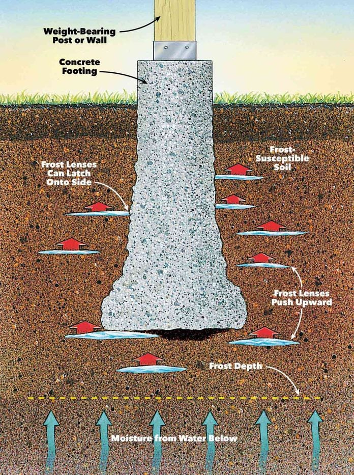
See The Codes
Click to jump to this section of these building codes:
IBC 2021 1809.5 – Frost Protection
FBC 2023 1809.5 – Frost Protection
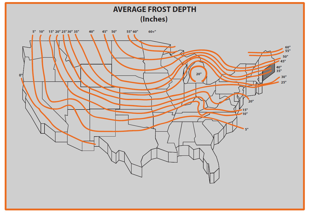
Example of frost depths throughout the US.
Please consult with your local engineer for updated and accurate values. this is for illustrative purposes only. Also try here.
3 Ways To Protect Footings Against Heave
The first method of frost protection specified in the code is extending the footing below the frost line also known as the frost front or freezing plane.
This depth varies and is determined based upon the governing municipality where the project is located.
The frost line can extend anywhere from 5 inches to 6 feet below grade in some Northern parts of the United States (see Average Frost Depth map).
The second method of frost protection is to construct the foundation in accordance with ASCE 32. This design standard specifies foundation construction to protect against the effects of frost via the installation of an insulation layer and non-frost susceptible layer which limits heat flow.
The third method of frost protection is erecting your structure on solid rock.
Alternatively, you could replace fine soil with granular soil below your structure which is not subjected to heave where site conditions permit you to do so.
What’s Exempt From Desiging For Heave?
Free-standing buildings are exempt from frost protection requirements granted the structure meets all of the following conditions:
> The structure must be Risk Category I
> The structure must have an area of 600 square feet or less for light-frame construction
> Or an area of 400 square feet or less for other light-frame construction, and eave height of 10 feet or less.
For More Information
See https://www.fhwa.dot.gov/publications/research/infrastructure/pavements/ltpp/08057/07.cfm
Also see http://www.hammerpedia.com/frost-line-map/
And https://www.weather.gov/ncrfc/lmi_frostdepthmap
& This related article: TYPES OF AT-GRADE FOOTINGS EXPLAINED
Tell us how can we improve this post?
What is a TER and how is it used for permitting?
TER – Technical Evaluation Report (Product Performance Evaluation) Explained
A TER or Technical Evaluation Report, is an engineering evaluation based on testing and/or rational analysis for the performance of a building product or component. In the case of Engineering Express, we are evaluating the structural aspects of a product only.
The authority for a qualified engineer to create a technical evaluation report is given in both the International and Florida Building Codes by an approved source (section 2.2). Numerous other codes are utilized in the creation of a TER which are listed on each corresponding evaluation report.
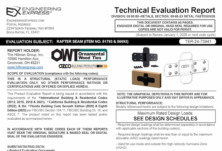
Why TERs Matter in Permitting
-
Limited product categories require approvals in Florida. Only eight building product categories need official product evaluations. -
TERs fill the gap. For everything else, TERs are a code-compliant method for showing product performance. -
Local flexibility. TERs can be applied under the Local Product Approval process for site-specific projects. -
Nationwide acceptance. Beyond Florida, TERs are recognized by the International Building Code (IBC) as valid evaluation reports.
Important
A TER defines a product’s tested or calculated limits, but it does not determine whether the product is appropriate for a specific project. That decision rests with the project engineer.
Example
A TER may show a beam can carry 10,000 lbs. Whether that beam is suitable for a specific building depends on the design plans and local conditions.
ICC & Florida Building Product Certification Requirements
The International Building Code (IBC) governs product approvals through:
-
Section 104.11 – Alternative materials, design, and methods (IBC 2021–2024, §104)
-
Section 1703 – Approvals
Florida Administrative Code 61G15-36 defines Product Evaluation Documents as:
Product Evaluation Documents. Engineering documents that define procedures, materials, devices, fabrication, and methods of construction and installation of a product, or standardized group of products, through product evaluation or rational analysis, with the objective of obtaining approval from the authority having jurisdiction of that product for installation. Product evaluation documents shall be generic and do not include documents prepared for a site specific project.
These codes let officials approve innovative products when supported by engineering analysis. The Florida Building Code (2023 FBC) reinforces this through FBC 104.11 and 1703 (Approvals), giving engineers a clear path to demonstrate compliance.
Why An Original Engineer Seal Is Required on Technical Evaluation Reports
Since these evaluation documents are not issued by an accredited evaluation entity such as ICC or Miami Dade Product Control, among others, each document must bear the original signature and raised seal of the evaluating professional engineer.
USEFUL ARTICLES
-
What Doesn’t a TER Do
-
Typical Reasons Why TER’s Aren’t Approved.
-
Denied a Building Permit with Our TER?
For guidance with your next project, explore our Plans, Calculators, Knowledge Base,
or contact us directly for site-specific support
Visit Our Plan Store
Online Design Calculators
Visit Our Knowledge Base
Site specific project request
Chat with a Designer
Chat with a Designer
Site specific project request
Visit Our Plan Store
Online Design Calculators
Tell us how can we improve this post?
Procedure For Calculating Aluminum Box Beams For Bending
Per the Aluminum Design Manual (ADM) 2015, the allowable bending stress of round tubes shall be determined for the limit states of yielding, rupture, and local buckling:
- that given by section F.6.1 (compressive yielding), or
- that given by section F.6.1 (tensile yielding), or
- that given by section F.6.1 (tensile rupture), or
- that given by section F.6.2 (upper inelastic buckling), or
- that given by section F.6.2 (lower inelastic buckling), or
- that given by section F.6.2 (elastic buckling)
Basically, the allowable bending stress is either the allowable tensile stress of the tension side of member (#2), the allowable compressive stress of the compressive side of the member considered as a whole (#1), or the allowable compressive stress of the member as governed by its individual elements (flange & webs) due to local buckling (#4, #5, and #6).
The allowable compressive stress of a member works in a similar way, but based on sections E.3 and E.4 for limit states of member buckling and local buckling, respectively.
Examples from the Aluminum Association are found by Clicking Here
Bottom line is this is a complicated procedure, let us help! Contact Us
Tell us how can we improve this post?
What’s the minimum penetration for lag screws into wood?
Per the 2015 National Design Specification for Wood Construction (NDS 2015), section 12.1.4.6, the minimum length of lag screw penetration Pmin not including the length of the tapered tip, E, of the lag screw into the main member of single shear connections and the side members of double shear connections shall be 4D where D = the diameter of the lag screw.
Refer to the NDS standard for more information including tables and other factors that affect lag screw strength or contact us for a consultation for your product or project.
Historical:
Per the National Design Specification for Wood Construction (NDS) 2012, Section 11.1.4.6 the minimum penetration (not including the length of the tapered tip) of the lag screw into the main member for single shear connections or the side member for double shear connections shall be four times the diameter, Pmin = 4Ø. A 1/2″ lag screw would therefore need roughly 4 * 1/2″ = 2″ penetration.
However, if you have 4Ø, that does not mean full capacity for the connection because in the tables of LAG SCREWS: Design Values, you will find footnote 3 which states that when the penetration is between 4Ø<=p<8Ø the lateral design loads values (Z) shall be multiplied by p/8Ø (penetration factor) or shall be calculated using the provisions of Section 11.3.
At first look in Section 11.5 Adjustment Factors for Dowel-Type Fasteners in lateral loads, there is no Cd (penetration Depth Factor) applied but the footnote referenced above refers to a specific section in order to calculate it.
Tell us how can we improve this post?
Minimum Edge Distance Requirements for Bolts & Screws in Metal (Steel & Aluminum)
Minimum Edge Distance Requirements for Bolts & Screws in Metal (Steel & Aluminum)
Proper edge distance is critical to avoid tear-out, maintain bearing strength, and ensure fastener installation tolerances in metal members.
Insufficient edge distance can lead to deformation or cracking near the edge of the metal, especially when larger fasteners or tight spacing are involved.
This article will guide you through the minimum edge distance requirements for steel and aluminum, helping you check your layouts, avoid common installation issues, and ensure your designs are up to code.

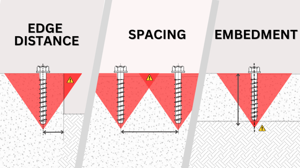
Want More on Fastener Design Basics?
For more information on edge distance and other key characteristics to watch for when designing with fasteners, take a look at our related article by clicking the button below.
Learn more on Edge Distance, spacing & embedment
Steel Edge Distance Requirements (AISC)
Minimum edge distances for bolts and screws in steel members are specified in the AISC Steel Construction Manual (15th Edition). The tables below provide the required minimum distance from the center of a standard bolt hole to the nearest edge of the connected steel part, based on the bolt diameter.
To select the correct minimum edge distance, first identify the hole type. If the hole is standard, simply use the value from Table J3.4 based on the bolt diameter. If the hole is oversized or slotted, add the small increment C₂ from Table J3.5 to the value in Table J3.4. The C₂ increment depends on bolt size and the type of slot, and ensures enough material remains around the hole for strength.
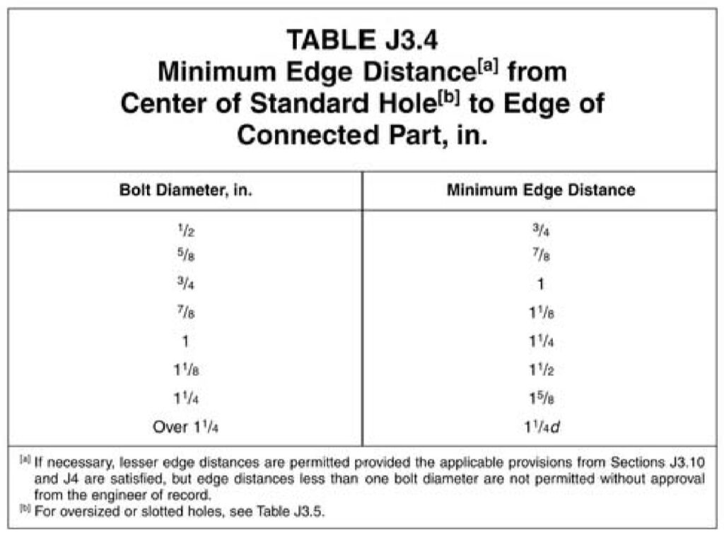
Minimum edge distances (AISC Manual 15th Ed., Table J3.4)
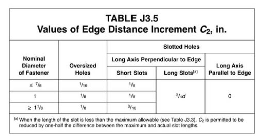
C₂ additions for oversized and slotted holes (AISC Manual 15th Ed., Table J3.5)
Our Recommendations & Cautions
– We recommend using more than the minimum edge distance whenever possible. It improves installation and reduces the chance of minor edge problems.
– These tables apply only to steel members. Aluminum has separate requirements covered in the next section.
– Edge distances smaller than one bolt diameter are not permitted unless specifically approved by the Engineer of Record.
– When in doubt, or when dealing with nonstandard hole types or tight layouts, verify the final edge distance with the Engineer of Record.
Aluminum Edge Distance Requirements (ADM)
Minimum edge distances for screws in aluminum members are defined in the Aluminum Design Manual (ADM), Section J.5.3, which specifies a minimum of 1.5D (1.5 times the screw diameter).
However, it is common engineering practice to use 2D or greater when layout space allows, since 2D typically develops full bearing strength without reduction. At 1.5D, bearing strength may be reduced, meaning the aluminum around the screw could deform or shear out before the screw reaches its full capacity. Some manufacturers therefore choose to recommend 2D edge distances to ensure their products are not weakened in the field.
Our Recommendations & Cautions
– We recommend using 2D or greater edge distance when possible, since this generally provides full bearing strength and reduces deformation near the edge.
– Verify with the Engineer of Record if working below 2D.
– When working with thin aluminum sections, larger screws, or high loads, verify edge distances with the Engineer of Record for safe performance.
This article has outlined the key requirements for edge distances in both steel and aluminum connections, but it’s important to verify that your specific design complies with the latest codes and project standards. When layouts become tight, loads increase, or nonstandard hole types are involved, always consult the Engineer of Record for final approval.
For more detailed information and professional support on your future projects, don’t hesitate to contact us. If you have any questions or want to learn more about our services, simply get in touch. Click the buttons below to get started!
Also, make sure to check out our other engineering articles for more valuable insights and tips!
For more detailed information and guidance on handling your future design projects, check out our online design calculators, contact us for site-specific projects, or reach out to us with your inquiries.
Online Design Calculators
Site specific engineering request
Chat with an engineer
Tell us how can we improve this post?
What’s the dimensional difference between a pipe and a tube?
There is often confusion as to which size product a client actually needs – Pipe Size or OD Tubing Size. Keep in mind that pipe size refers to a nominal – not actual – inside pipe diameter. Schedule refers to the pipe’s wall thickness. The dimensions provided for OD tubing on the other hand refer to the actual outside diameter and wall thickness.
For example: 1-1/2″ pipe size flanges have an opening to fit over 1.90″ OD – the actual outside diameter of 1-1/2″ pipe – while 1.50″ OD tubing has a true 1.50″ outside diameter and the flange is sized accordingly. See below for illustration.

Tell us how can we improve this post?
What is a window or door buck
What Is A Window Or Door Buck?
Openings in buildings are frequently not exact and are referred to as rough openings for that reason.
When window products are placed into openings, they often need to be shimmed into place to properly fit the opening.
Sometimes, windows come with a ‘fin’ that requires a buck to serve as a support for this lip surrounding the frame.
When a large amount of shimming is required, 1x or 2x pieces of wood are utilized and are referred to as door bucks.
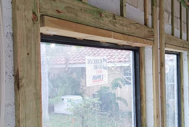
Code References
Product evaluations issued by accredited entities specify how to fasten window products to host substrate with a maximum shim thickness.
However, if the window is only fastened to the buck, then the buck needs to be securely fastened to the host structure.
According to Section 1710.3 of the 2023 Florida Building Code (8th Edition).
“where the wood buck thickness is 1 ½ inches (38 mm) or greater, the buck shall be securely fastened to transfer load to the masonry, concrete or other structural substrate…”.
In the 2021 International Building Code more loosely covers buck attachment in Chapter 23.
More On The Topic of Wood Bucks
It’s typically up to the Window or Door Product Manufacturer to specify whether bucks can be used and how they may be installed.
A general rule is that a 2X wood buck (1.5″ actual thickness) should be installed at least as securely as the window or door anchorage being installed to it.
In the case of impact windows, the maximum force shall be used and not reduced for a lesser force or opening area.
for 1X wood bucks (0.75″ actual thickness), it is possible that the window or door anchors may pass through the 1X buck and provide equivalent embedment to provide a ‘solid shim’ condition and equivalent anchorage*.
Wood bucks also provide an aesthetic finish and assist in flashing & waterproofing of the building envelope.
Stucco finishes typically encase wood bucks and sealed with caulk.
* Always consult a design professional before installing wood bucks as there are many factors to consider that are beyond the scope of this article.
Contact us to discuss your need.
From Our Plan Store
Engineering Express provides pre-engineered certified plans to assist in permitting wood bucks in our online plan store.
View these plans which describe 2x & 1X wood buck installation.
Purchase engineer-sealed copies to be used with your project for plan review and construction documentation. Plans are sealed for use in your state throughout the US.
Tell us how can we improve this post?
Should a professional utilize the ASD (Allowable Stress Design) method or the LRFD (Load Resistance Factored Design) method when calculating the required wind pressure for use with tested-approved systems?
What’s The Difference Between ASD & LRFD Design?
Put in layman’s terms, think of a wood plank designed to stretch between two supports.
You’re going to walk across the piece of wood.
The person that designed that plank needed to figure out if it will hold you.
They had two options when designing:
1) Reduce the calculated capacity of the plank to provide the necessary safety factor (so say a plank that can hold 300lb is ‘rated’ for only 200lb) – This is the ASD Method.
2) Increase your weight and design for that higher load (hence the elephant in the image), so a 200lb person becomes a 300lb person. This is the LRFD (Ultimate Design) method.
It’s important to understand which method is being used in a chart, table, calculator, or design, and to utilize that method across the design.
ASD History
Many years ago, the ASCE wind speed map was replaced from ASCE to LRFD.
The new wind maps are now specified at the strength design level (Load Resistance Factored Design, or ultimate load) rather than the service design level (Allowable Stress Design).
A load factor increase was integrated into the design wind speeds specified in the ASCE maps.
…You may recall one used to hear ‘140mph winds’ used to describe category 5 hurricanes in Florida which is now ‘170mph winds’. It’s the same force, only ultimate instead of allowable.
Use In Product Approved Building Component Design
Most product evaluation approvals are tested in service design conditions (ASD), but should be confirmed within each product approval’s limitations of use.
Generally speaking, test protocols provide a test pressure and/or failure load which already include a safety factor for the design pressure. Thus, by the very nature of having built-in safety factors during testing, most of product approvals are inherently forced into ASD.
It’s recommended to consult a design professional before using any result from a table in your project.

This table is an example of one of the minority of uses of ultimate load values in product approvals.
The user is instructed to multiply the table loads by 0.6 before using them with ASD wind pressures. This format for designing is difficult to understand, out of the ordinary, and will lead to safety installation issues during design events.
It is NOT recommended that tables be displayed in this manner without significant instruction and warning.
Most construction building products sent to product approval agencies use the ASD method for design.
A designer may ask, “Aren’t the design pressures for these components reduced by the 0.6 factor?” The answer is very simple: the pressure is not reduced, it is a completely separate type of analysis.
If a building component was analyzed with a demand such that the LRFD factor was used, the component itself would have an LRFD capacity that would be much higher than if the capacity was analyzed using the ASD method. As an example, a component could have a demand of 100 kip-in using LRFD, or a demand of 60 kip-in using ASD.
The component can ALSO have a capacity of 1000 kip-in using LRFD, OR a capacity of 600 kip-in using ASD, as each method uses separate design factors. The component still has the same strength and is approved in both scenarios. They are apples to apples and oranges to oranges.
The Allowable Stress Design approach seeks to maintain serviceability by using safety factors to ensure that applied loads do not exceed the elastic limit. This is why ASTM E330 and others require a safety factor of 1.5 up to 2.0.
IMPORTANT: With Load Resistance Factored Design (strength design) the approach is to avoid failure by increasing required loads through the application of load factors to obtain the ultimate required strength load and compare this to the ultimate factored strength capacity, whereas with Allowable Stress Design (service design) the approach is to avoid failure by decreasing allowable loads through the application of safety factors to obtain the allowable service capacity and compare this to the required service demand.
Applied To Building Codes
2023 FBC Section 2404.1: (other code versions are similar to date) The design of vertical glazing shall be based on the following equation:
0.6Fgw ≤ Fga (Equation 24-1)
where:
Fgw is the wind load on the glass computed in accordance with Section 1609
Fga is the short duration load resistance of the glass as determined in accordance with ASTM E 1300.
From 2023 FBC (other codes similar to date)
1609.1.2.4 Impact resistant coverings.
1609.1.2.4.1 Impact resistant coverings shall be tested at 1.5 times the design pressure (positive or negative) expressed in pounds per square feet as determined by the Florida Building Code, Building Section 1609 or ASCE 7, for which the specimen is to be tested. The design pressures, as determined from ASCE 7, are permitted to be multiplied by 0.6.
See more on IBC 2021 Building Code in section 1609.1.2.
Tell us how can we improve this post?