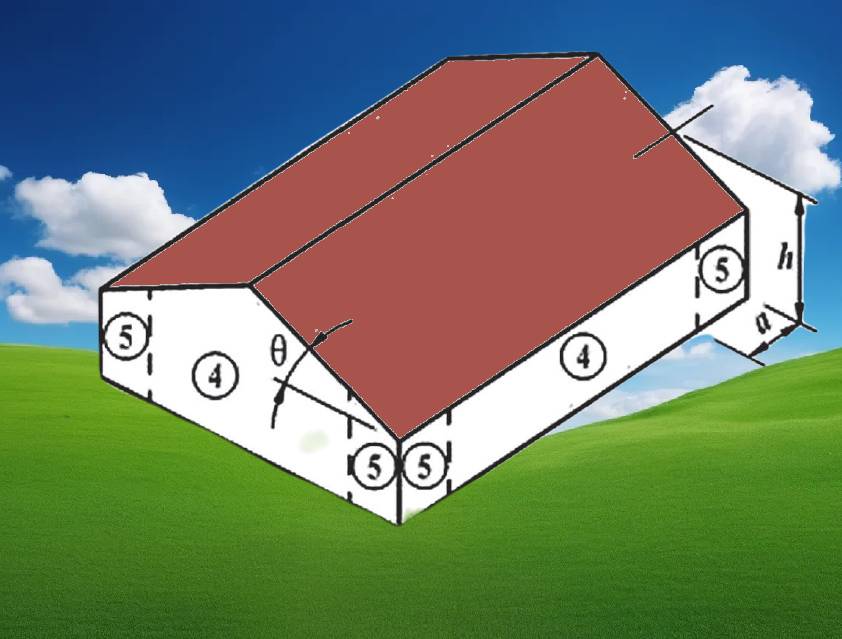
ASCE 7 Wall Zones Explained

ex logo

ASCE 7-16 has expanded on the definition of component & cladding wind zones from previous ASCE 7 standards.
ASCE 7-22 continues with this definition.


Per ASCE 7-22 &16, buildings are composed of 5 different zones, depending on the wind loading they are subjected to.

Zones ‘4’ & ‘5’ relate to wall zones & are defined as follows:

Zone 4: Any areas between the wall corners that are not included within Zone 5.

Zone 5: 10 percent of least horizontal dimension or 0.4h, whichever is smaller, but not less than either 4 percent of least horizontal dimension or 3 ft (0.9 m).


Key Terms and Definitions:

Mean Roof Height (h)

Least Horizontal Dimension

More on Component & Cladding


Analysis

An analysis of wind pressure acting on a building component (window, door, etc.) is performed depending on what zone it is in (see illustrations below).  Chapter 2411.1.8 of the 2020 Florida Building Code (HVHZ) permits Zone pressures that fall between two zones to be interpolated up to a maximum of 50% in zone 5, providing a documented interpretation of the code in a high-risk area.  Use our  ASCE 7 Zone Interpolator Calculator to interpolate your application.  Certified results can be reviewed and provided for permit.

It is important to note that the intent of the code is a ‘lite’ of glass – If several units are mulled together with a structural break, each unit as well as the structural break shall be considered separately.

The interpretation of zones should be left to a licensed professional engineer when in doubt.  Otherwise, the most critical zone is suggested.

Below is a video that helps illustrate how the zone 5 vortexes form and how better to understand the theory of the zone 5 effect.  Keep in mind when watching that the wind has to come from an opposing direction (all structures are analyzed with wind approaching from all angles), and create the turbulent effects in the video.  Areas protected from the turbulent effect are generally not wind zone 5.


Helpful Illustrations


Additionally per AAMA TIR A-15-14, zones 4 & 5 can be further explained as:

170 Degrees: Unobstructed exterior corner is considered Zone 5 if the angle < 170 degrees open as shown

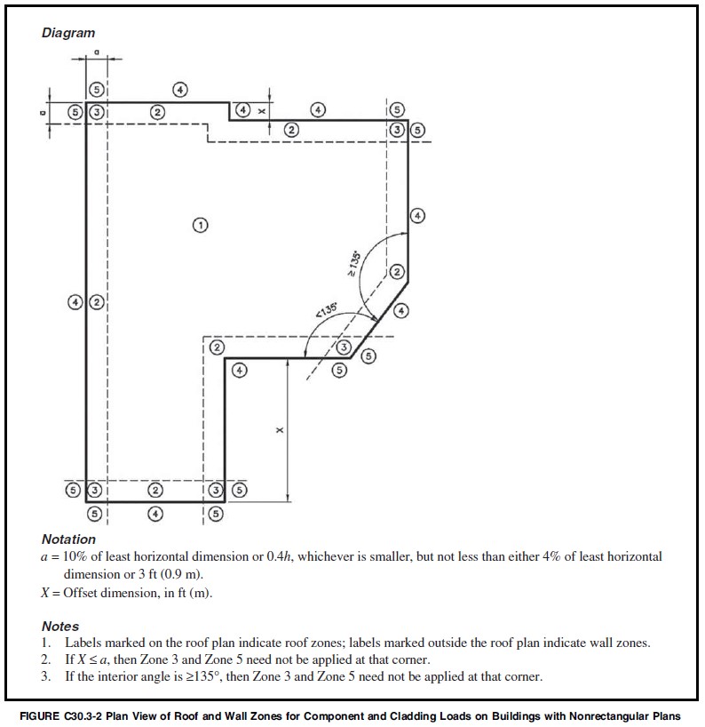
Note on this designation: ASCE 7-16/22 uses a 135-degree designation instead of 170 degrees, explaining in Figure C30-2 (below) that roof zone 3 and wall zone 5 need not be applied at that corner. The difference refers to engineering judgment of ‘building corner discontinuity’ and ‘wind flow separation’. This is also a possible solution that is for consideration at the discretion of the reviewing design professional. The more critical has been illustrated here for purposes of providing a more generalized design solution.
(Updated 2-2022 from user feedback).


ASCE 7 also published a commentary that explains wall and roof zone areas.  From the below figure, more information is shown to describe further how zones 4 and 5 are determined:

Wall and Roof Zones Explained Per ASCE 7


Watch this video to help better explain how end-zone 5 vortexes form


Last Update: February 15, 2024  

March 27, 2021  Codes & Standards  
Total 36 Votes:

Tell us how can we improve this post?

+ = Verify Human or Spambot ?

Scroll to Top