Minimum Edge Distance Requirements for Bolts & Screws in Metal (Steel & Aluminum)
Proper edge distance is critical to avoid tear-out, maintain bearing strength, and ensure fastener installation tolerances in metal members.
Insufficient edge distance can lead to deformation or cracking near the edge of the metal, especially when larger fasteners or tight spacing are involved.
This article will guide you through the minimum edge distance requirements for steel and aluminum, helping you check your layouts, avoid common installation issues, and ensure your designs are up to code.

Want More on Fastener Design Basics?
For more information on edge distance and other key characteristics to watch for when designing with fasteners, take a look at our related article by clicking the button below.
Steel Edge Distance Requirements (AISC)
Minimum edge distances for bolts and screws in steel members are specified in the AISC Steel Construction Manual (15th Edition). The tables below provide the required minimum distance from the center of a standard bolt hole to the nearest edge of the connected steel part, based on the bolt diameter.
To select the correct minimum edge distance, first identify the hole type. If the hole is standard, simply use the value from Table J3.4 based on the bolt diameter. If the hole is oversized or slotted, add the small increment C₂ from Table J3.5 to the value in Table J3.4. The C₂ increment depends on bolt size and the type of slot, and ensures enough material remains around the hole for strength.
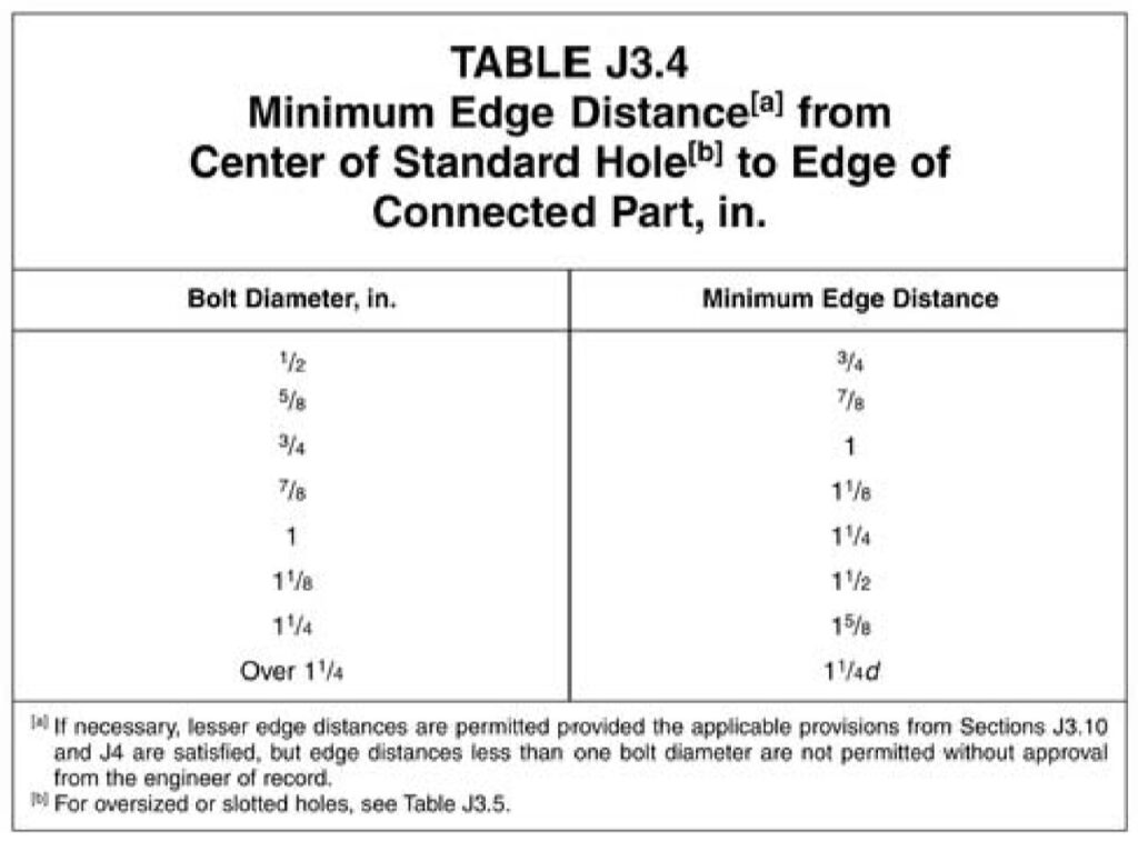
Minimum edge distances (AISC Manual 15th Ed., Table J3.4)
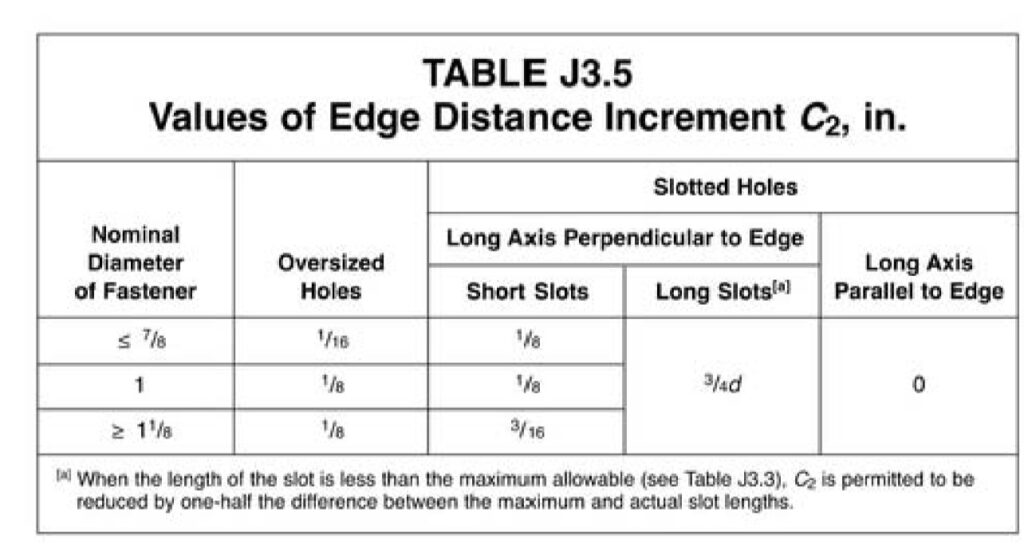
C₂ additions for oversized and slotted holes (AISC Manual 15th Ed., Table J3.5)
Our Recommendations & Cautions
- We recommend using more than the minimum edge distance whenever possible. It improves installation and reduces the chance of minor edge problems.
- These tables apply only to steel members. Aluminum has separate requirements covered in the next section.
- Edge distances smaller than one bolt diameter are not permitted unless specifically approved by the Engineer of Record.
- When in doubt, or when dealing with nonstandard hole types or tight layouts, verify the final edge distance with the Engineer of Record.
Aluminum Edge Distance Requirements (ADM)
Minimum edge distances for screws in aluminum members are defined in the Aluminum Design Manual (ADM), Section J.5.3, which specifies a minimum of 1.5D (1.5 times the screw diameter).
However, it is common engineering practice to use 2D or greater when layout space allows, since 2D typically develops full bearing strength without reduction. At 1.5D, bearing strength may be reduced, meaning the aluminum around the screw could deform or shear out before the screw reaches its full capacity. Some manufacturers therefore choose to recommend 2D edge distances to ensure their products are not weakened in the field.
Our Recommendations & Cautions
- We recommend using 2D or greater edge distance when possible, since this generally provides full bearing strength and reduces deformation near the edge.
- Verify with the Engineer of Record if working below 2D.
- When working with thin aluminum sections, larger screws, or high loads, verify edge distances with the Engineer of Record for safe performance.
This article has outlined the key requirements for edge distances in both steel and aluminum connections, but it’s important to verify that your specific design complies with the latest codes and project standards. When layouts become tight, loads increase, or nonstandard hole types are involved, always consult the Engineer of Record for final approval.
For more detailed information and professional support on your future projects, don’t hesitate to contact us. If you have any questions or want to learn more about our services, simply get in touch. Click the buttons below to get started!
For more detailed information and guidance on handling your future design projects, check out our online design calculators, contact us for site-specific projects, or reach out to us with your inquiries.
Last Update: December 30, 2025
Related Knowledge Base Posts -
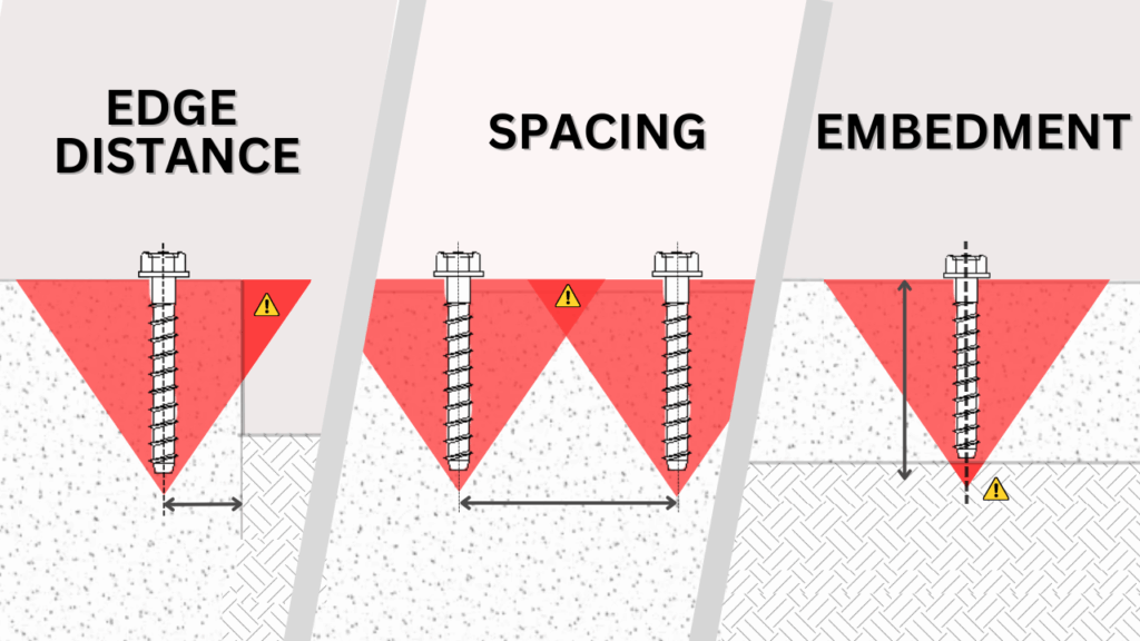
- Why are spacing, edge distance, and embedment important for concrete anchors?
- What is a window or door buck
- Metal Fasteners UNC vs Spaced Thread
- Loss of Capacity Due To Welded Aluminum In Railings – Signs – Structures
- What’s the minimum penetration for lag screws into wood?
- ASTM, SEI, ISO Fastener Material Properties and Specifications