At Engineering Express, we pride ourselves on the quality of our work. Consistency is the key to a nicely presented set of engineered drawings.
This article explores several guidelines we follow when creating structural shop drawings for our clients or modifying drawings provided to us.
Title Blocks:
If you elect to use your own borders for our final work, it’s necessary that your borders conform to minimum standards. Contact Us to discuss and have us help you.
- Layers:
Take advantage of AutoCAD layers and always sort different drawing elements in their respective layers. This allows to freeze all dimensions if required or lock everything in the drawings except, for example, the detail call outs for ease of selection.
- Scale:
It is good practice to draw EVERYTHING in true scale (1:1) in Model Space and use AutoCAD’s Viewports in Paper Space to give the drawings their proper scale.
Floor plans are usually drawn at 1/8” = 1’-0”*
Glazing elevations are usually drawn at 3/8” = 1’-0”*
Details are usually drawn at 6” = 1’-0”*
*These are guidelines based on drawings done in an 11” X 17” format, scale for a 24”x 36” format will be double the one used in 11”x17”. Scales can be altered depending on the true size of the elements drawn, therefore it’s very important to draw at true scale (1 unit = 1”).
- Dimensions:
Another crucial reason to draw everything in true scale is to have consistent dimension and text sizes throughout the drawing set. Dimension Styles should be adopted based on the scale used in Paper Space (follow the factoring table below):

- Notation:
Just like in Dimensions, text styles should match the Dimension styles to have consistency in the drawings.
It is good practice to place detail callouts “aligned” horizontally and vertically on the glazing elevations, this not only more visually pleasing and easier to read but also serves a purpose when it’s time to select the detail callouts for copy/ paste operations.
Detail callouts should have a number on top referring to the detail number and a number below the detail number referring to the page where the detail can be found (see image above).
- Blocks:
It is recommended when having repetitive elements in a drawing (eg. Title Block) to make it as a Block, it is extremely helpful and time saving when information such as revision dates need to be added to several pages in the drawing. Learn more about blocks by clicking here.
- Cover sheet:
Being the first line of information in a set of drawings, this sheet is packed with useful and vital information. It must show the Project name & address, Building Code used, General Notes, wind pressure criteria, Systems used (including product approval numbers, glass types used and system finish), scope of work and Index, in addition to detailed design information, company information, PE information and company certificate of authorization (as applicable).
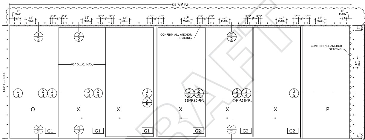
Elevations:
Opening elevations should always reflect the correct dimensions based on the system used, depending on the system used, the members of a glazing system may present different profiles, it is important to draft the elevations with the correct profiles to get accurate day light opening dimensions (D.L.O). Always dimension the elevation including Rough Opening (R.O.), Frame Size (F.S.), Day Light Opening (D.L.O.).
Also display under the elevation, it’s designated Mark (shown also in the floor plan to locate the opening), manufacturer (including product approval number), quantity of openings, and Design Wind Pressures.
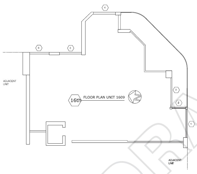
- Floor plans:
Floor plans are useful to show the location of the openings in the scope of work within the building. It also helps to determine Building End Zones for wind pressure calculations. The openings in the floor plan should be clearly identified with a hexagon call out and usually a letter.
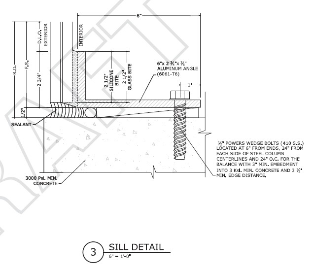
- Details:
Glazing details are usually drawn in scale 6”=1’-0” (when using an 11”x 17” format). These details must include dimensions showing R.O., F.S., D.L.O., (rough opening, frame size (after shim space), daylight opening (the part that’s completely see-through) – see image) profile size, system depth, shim space and glass bite. Also must include substrates based on architectural drawings and proper anchorage based on respective product approvals and exterior / Interior sides must be clearly identified.
Remember, this is all PRE-ENGINEERING and subject to engineer review and approval by the firm. Engineering notes would then need to be added, calculations made, consultation with the client, and the plans must be certified by a licensed professional engineer prior to use of any kind. Contact us to discuss your drafting and engineering needs or submit a quote request through our innovative order system for the department of your need..
Last Update: February 25, 2025