Perforated Design Method vs. Segmented Design Methods for Shear Walls
The International Building Code (2018) defines a shear wall as “a wall designed to resist lateral forces parallel to the plane of a wall.” Lateral forces include, but are not limited to, wind and seismic forces that may shift or deflect a structure laterally.
2 Design Methods
Two design methods can be utilized by engineers and designers; The Perforated Design Method and The Segmented Design Method. There are other design methods, for example, the Force Transfer Approach, however the two design methods discussed in this article are common and widely used. The distinguishable difference between these methods is a factor of the shear wall’s construction. A perforated shear wall is “a wood structural panel sheathed with openings, that has not been specifically designed and detailed for force transfer around openings” (IBC 2018). In terms of design, this means that the segments of the shear wall containing openings for windows and doors CANNOT be used as lateral force resisting systems.
The Special Design Provisions for Wind & Seismic (2015) by the American Wood Council describes the Segmented Design Method in Section 4.3.5.1. A limitation on using this design method is that the segment must not exceed the height-to-width ratios described in SDPWS (2015) Table 4.3.4, illustrated below. In addition, per SDPWS (2015) Section 4.3.5.1, “collectors for shear transfer to individual full-height wall segments shall be provided” where openings occur.
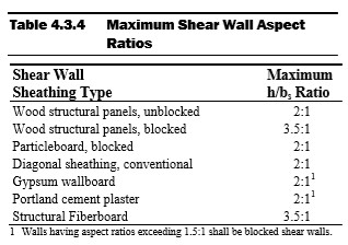
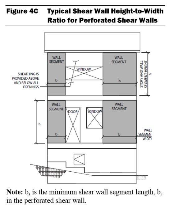
The Perforated Design Method assumes that all openings in the shear wall are able to transfer the loads from around the opening to full-length segments. This means that the full length of the wall, including segments with openings, can be included in the lateral force resisting system. The aspect ratios in Table 4.3.4 above are applicable for the Perforated Design Method as well. See SDPWS (2015) Figure 4C below describing the height (h) – to – width (b) ratio and that definition of a wall segment. It may seem that any shear wall may be designed using the Perforated Design Method, as it allows shear wall segments above and below openings to be accounted in the capacity of the lateral force resisting system. However, the Perforated Design Method may not be used with walls with non-uniform top-of-wall and bottom-of-wall elevations, per SDPWS (2015). In addition, shear wall height may not exceed 20 feet. If a shear wall has non-uniform elevations and/or the height exceeds the limit described in SDPWS (2015) Section 4.3.5.3, more complex methods of analysis will be necessary.
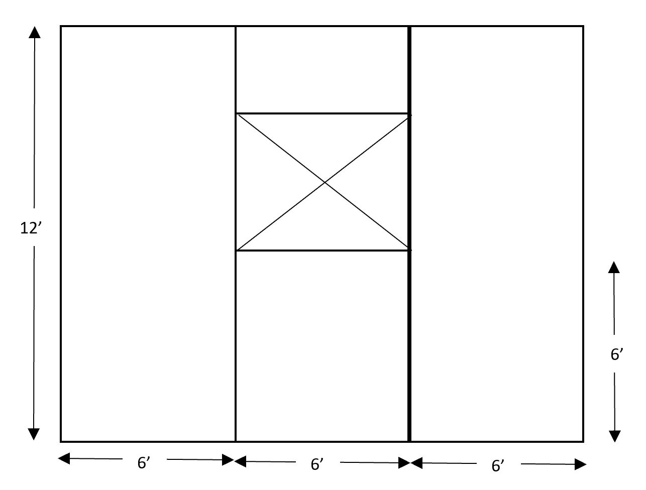
A sample shear wall calculation is performed below, finding the shear capacity of a 12’ wall with three 6’ segments. The first segment is full height, the second has a 3’ window 6’ above grade, and the last segment is full height. See the figure below for clarification. The top plate, bottom plate, and studs are to be Southern Pine with a specific gravity of 0.55. OSB Sheathing is 7/16” and a 32/16 APA span is used. Studs are spaced 16” o.c. and the panels are fastened using 8d common nails. A distributed live load of 80 plf and a distributed dead load of 40 plf are acting downward on the system. In addition, a 8 plf uplift force is acting on the system and there is a concentrated shear at the top of 1,000 lbs. The wall weighs 1 psf and is constructed in a region where seismic does not govern. Panel edge fasteners are assumed to be spaced 6”.
The example shown will start by solving the capacity of the wall using the Segmented Design Method. As stated, the Segmented Design Method does not consider any panels with openings, therefore, the middle segment cannot be considered.
The first step is the group the loads. The dead loads from the above the wall and the weight of the boards will be added to find total dead load the system must resist. To find the self-weight of the wall along the bottom of the plywood, the weight in psf is multiplied by the height in feet. This gives a self-weight of 12 plf. Added to the dead load above the wall, we have a total dead load along the bottom of the wall of 52 plf. The 52 plf dead load is added to the 80 plf live load to find a total downward force of 132 plf. The shear in the collectors throughout the wall is equivalent to the shear at the top of the wall (1,000 lbs) divided by the total length of the segments resisting the shear. Because the middle segment is not resisting the shear, the length of the wall is taken as 12’. The collector is experiencing 83.33 lb/ft of shear. This is also known as the unit shear, or Vm .
Next, the shear capacity of the plates and studs are considered. Using Table 4.3A from AWC’s SDPWS (2015), the nominal unit shear, vw, is 365 plf. A 2.0 multiplier is used per SDPWS (2015) 4.3.3. Per footnote 3 of Table 4.3A, a specific gravity multiplier is not necessary. A final unit shear capacity for the system is 730 lb/ft for the plates and studs.
The total shear wall capacity is taken as the 730 lb/ft multiplied by the length of the wall resisting the load, 12’. The total shear wall capacity is 8,760 lb. The wall is able to resist the full applied shear of 1,000 lbs.
The same calculations can be performed using the Perforated Design Method. The difference here is found in the unit shear calculation. Unlike the Segmented Design Method, the Perforated Design Method considers a few more adjustments. The Perforated Design Method takes in account the Maximum Opening Height Ratio (MOHR). This is taken as the height of the opening. In this example, the bottom of our 3’ window is 6’ above grade, resulting in a MOHR of 9’. The Maximum Opening and Wall Height Ratio is then considered as the maximum height of the opening divided by the height of the wall. 9’ divided by 12’ results in a 0.75 maximum opening and wall height ratio. The last adjustment needed is the Shear Capacity Adjustment Factor, Co, described in SDPWS (2015) Equation 4.3-5. To calculate Co, the Sheathing Area Ratio, r, needs to be calculated using SDPWS (2015) equation 4.3-6. The calculation of Co and r is below.
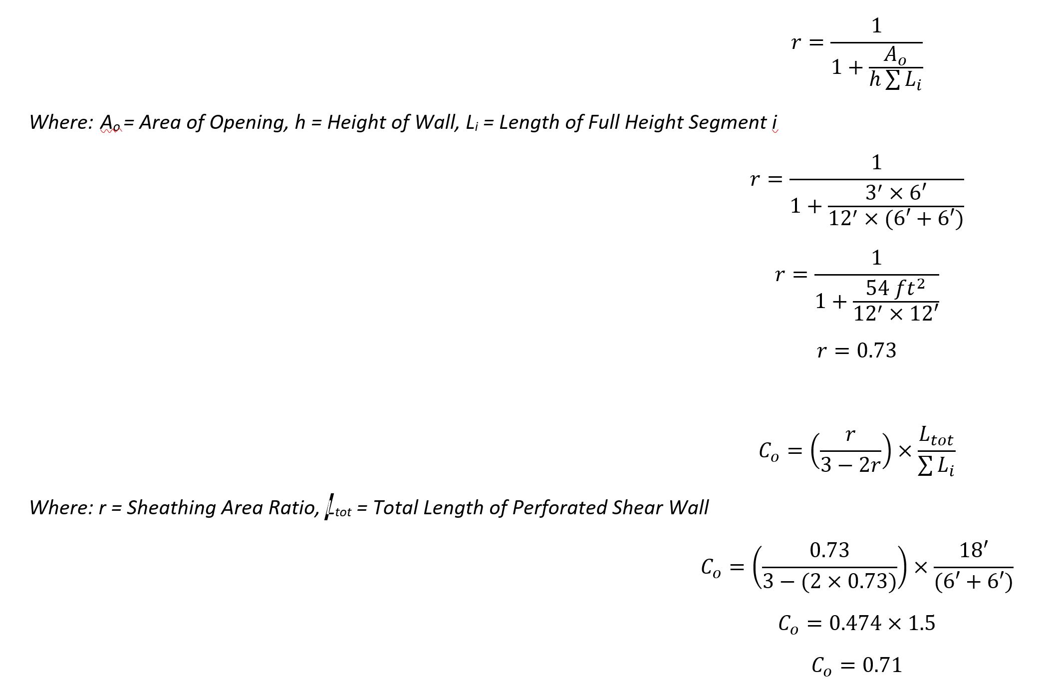
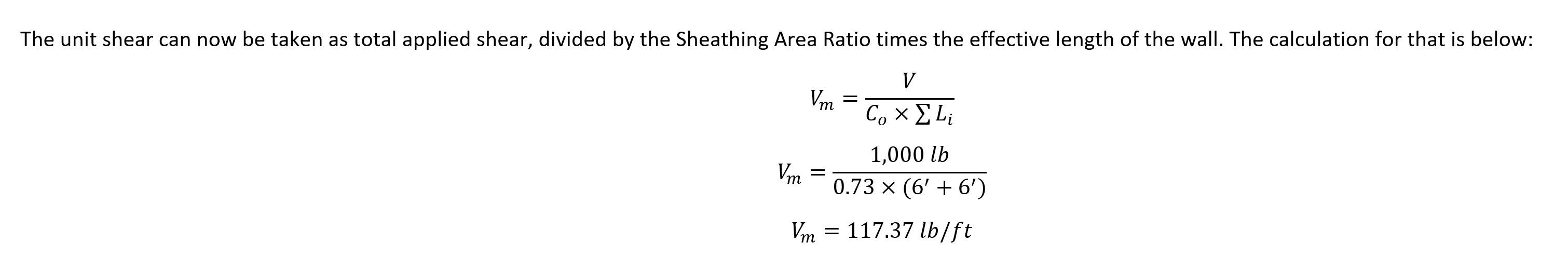
Using the Perforated Design Method, we found that the unit shear along the top and bottom of the shear wall is greater due to the opening in the wall. This means that a greater number of anchors would be needed around the edges of the system to account for the greater unit shear.
Engineering Express offers their clients a state-of-the-art calculator to calculate the needed anchors in a shear wall. The calculator uses empirical data and equations specified in codes and standards to determine the capacity of the shear wall itself and the anchors for shear walls of varying materials and sizes with up to 5 openings.
Calculation results can be reviewed and certified by a Professional Engineer for permit from Engineering Express. Click here to try the calculator out at no charge or obligation.
Contact Us to discuss your job specific or calculator need.
Article by Alexis Boden, EI, Project Designer, Engineering Express
Last Update: April 1, 2022