Porosity - How 'Open' A Surface Is - Explained
The porosity of open structures is defined in ASCE-7 standard under ‘open signs’ (chapter 29, as of ASCE 7-22).
This standard explains that the permeable (wind) porosity of a surface isn’t always equivalent to the calculated visual porosity.


Left: mechanically articulating louvers that can reach a porosity greater than 50%.
Top: Open fence, similar to an open sign.
The actual porosity should always be determined by a design professional, but here’s a guide.
ASCE 7 figure 29.3-1 note 2 points out two significant elements relating to porosity:
1 – Signs [and similar surfaces since mother nature doesn’t know the difference] less than (<) 30% open, porosity shall be permitted to be multiplied by the reduction factor
If Porisity < 30% open, Porisity = (1-(1-∈)^1.5)
where ∈ = the ratio of solid area to gross area.
For Example, for a surface 25% visually open (75% solid) : (1-(1-0.75)^1.5) = 0.875 or 87.5% solid for wind calculations.
2 – For open surfaces >= 30% open, the porosity calculation shall be taken as the visual (see-thru) calculation.
However, one must also consider the accumulation of debris, ice & snow on the surface in question when thinking of porosity for wind.
There are additional items to consider such as where the resultant force acts normal to the face or normal at a distance from the geometric center toward the windward edge (note 3 case A, B) or case C which goes further into analysis in ASCE 7 Chapter 29 which we encourage seeking professional assistance on in this porosity determination.
Fence Porosity - A Case Study
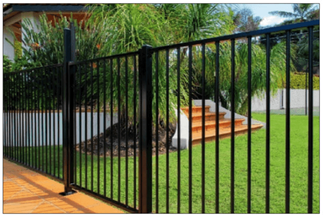
Take for example a fence or railing that is required to be 75% open (such as in these Lighthouse Point FL Building Code Amendments & many similar along the coastlines).
This porosity value is also frequently seen in the requirement of a barrier to be designed such that it resists a 4″ sphere.
The Porosity Calculation
Take for example the use of 3/4″ pickets and a 2″ railing/fence post to reject a 4″ sphere.
If the desired 75% porosity calculation is required for view-thru, using these values,
If this calculation came to be less than 30%, the above calculation would need to be used to determine the wind porosity which would differ from the visual porosity.
What To Do Next
Once the porosity of an opening is calculated, one must use ASCE-7 to determine the net force on a surface.
That is performed through a series of calculations in ASCE 7 Chapter 29 from the formula
F = qz * Kd * Gcf * Af
The review of this formula is beyond the scope of this article, but there are a few takeaways:
1 – qz is the force at height ‘z’ – meaning the higher the installation on a building (such as on a rooftop), the larger the force.
2 – CF – This is a force coefficient which varies depending on the type of surface the wind is flowing through.
> Interesting to note that flat-sided members yield a higher value of Cf (and consequently a larger force F) than rounded members which follow a Cf calculation based on porosity and shape as described in ASCE 7-22 Figures in 29.4.
Also, calculation of wind force (F) is performed normal (perpendicular) to the surface.
It is clear that an experienced design professional is needed to accurately account for all of these factors and variables.
Help Getting These Forces
You can purchase an engineer-certified, pre-engineered performance evaluation for permit that have tables which convert wind speed to pressure for a variety of situations. There is a free sample available for inspection before purchase.
We also have an online calculator that provides more precise answers and can help with the design. Find the wind speed-to-pressure calculator by clicking here.
Consequences Of Improper Louver Porosity Calculations
This article focuses on the calculated porosity of open louvers (surfaces) to resist uplift.
However, a prudent design would consider the need to lock louvers in the open position and for mechanical failures that could compromise pergolas.
Also, something called ‘continuous load path’ is equally as important – all the links of the chain need to be considered.
For a proper design, one must review the column base, head, and all remaining connections and elements.
We leave you with this video of an unknown pergola failure caught by a security cam of a failure in relatively low storm winds.
Engineering Express® can help you with all your louver, fence, railing, sign and gate needs using a variety of our state of the art resources. Browse our Online Store for pre-engineered plans, browse our expanding array of online calculators, or request a quote for a site-specific project in any of the 40+ states to which we are licensed.
Contact us to discuss your design needs and work through porosity considerations for your product or project.
Last Update: February 17, 2025
Related Knowledge Base Posts -
- Should a professional utilize the ASD (Allowable Stress Design) method or the LRFD (Load Resistance Factored Design) method when calculating the required wind pressure for use with tested-approved systems?
- ASCE 7 WIND EXPOSURE CATEGORIES AND HOW EXPOSURE ‘D’ WORKS
- Why are spacing, edge distance, and embedment important for concrete anchors?
- What wind information is required for construction documents?
- Understanding Canopies: Design and Load Considerations
- What’s the dimensional difference between a pipe and a tube?