Canopies & Wind Uplift - An Introduction
First, Understand This
A backyard canopy or pergola, trellis, or a lightweight sunroom/screen room attached to the back of your house are of relatively very little weight and are typically lighter in construction than the structure to which they are attached to.
Also, consider that a house wall continuously supports a roof, whereas a canopy is supported only at the corners or widely spaced posts.
These factors create the critical uplift forces on canopies resulting from wind.
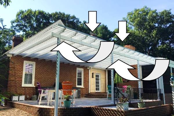
Uplift from wind puts instant, magnified forces on post connections at the head & base connection, as well as the foundation itself.
ASCE 7 contains expanded sections on how to handle these forces. More about the expanded sections of carports & canopies in the latest ASCE 7 code can be found from this article.
There’s also the question of porosity – Many think that something 50% open is 50% porous – but wind doesn’t always act that way. Read why.
Wind Uplift Design
So how does one design for uplift for a lightweight carport or canopy?
Understand this is a simplified analysis which a licensed professional must review before use. There are other forces in play – factored loads, snow, seismic, and heave to name a few which all have to be considered. But if you’re looking for a starting point, read on.
1 – After subtracting for dead loads (the self-weight of the structure), a designer must consider the net uplift force on the canopy/overhang.
The net uplift is the gross total uplift minus the gravity loads.
2- Then, consider the ‘tributary’ or ‘contributing’ area of the wind uplift force on each component it acts upon.
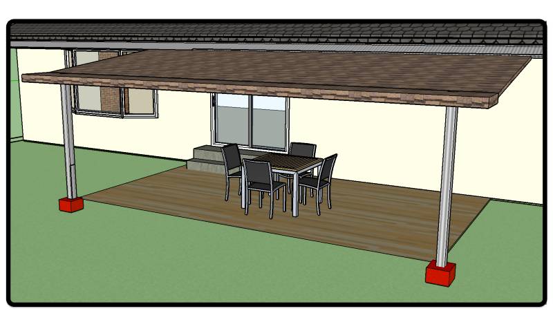
Take for example a host supported 3-post canopy as per this illustration:
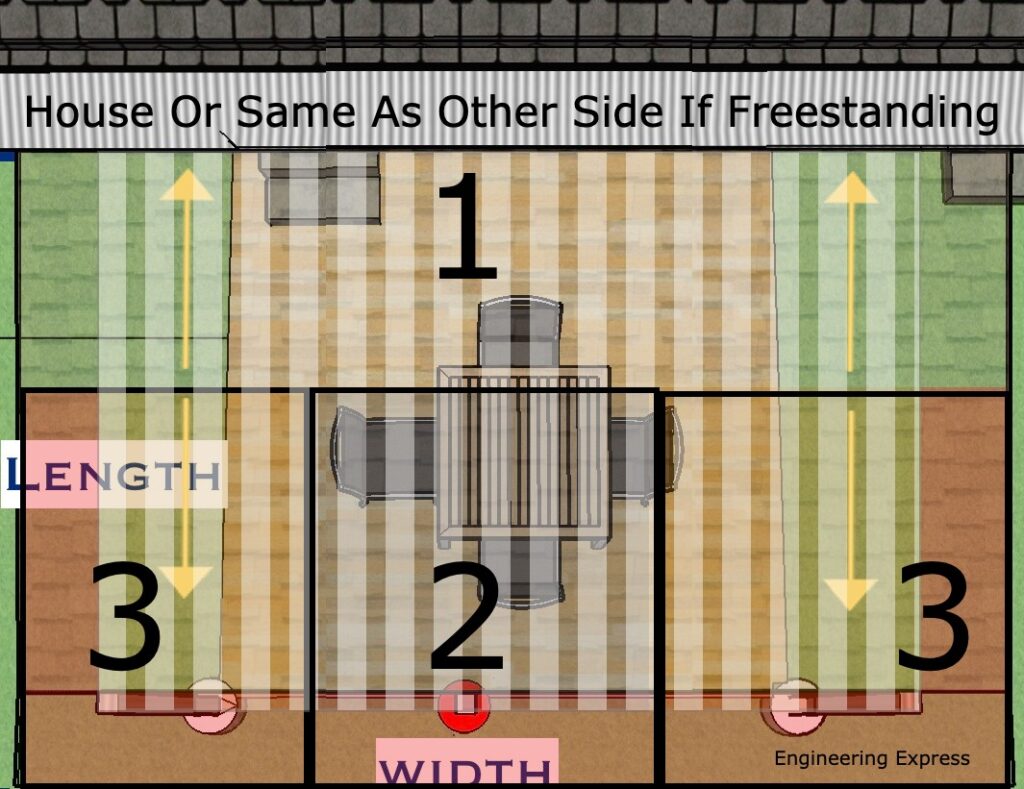
The tributary area on each outer post (area 3) is (1/2 the span (length) projection + the outer overhang) * (1/2 the column span width + the side overhang tributary area).
The tributary area on the center post (area 2) is (1/2 the span (length) projection + the outer overhang) * (1/2 the distance to the left column + 1/2 the distance to the right column).
The rest of the tributary area (area 1) goes to the main residence which is handled by the host structure connection.
In the case of a freestanding canopy/pergola, repeat the process for areas 2 & 3 for area 1.
To determine the net uplift force on each post, multiply each post’s tributary area by the net uplift force per square foot.
Determining The Net Uplift Force
Again, this is something for a design professional to assist with as many factors determine this (such as topography, exposure, risk category, among others).
This generally involves finding the applicable wind velocity and converting that speed into a wind force. We have another article that dives deeper on this topic.
Uplift Resistance - Not As It Seems
One might think the weight of the concrete/foundation needed to resist the uplift force is the answer, but there has to be a Factor of Safety acting against this force.
Concrete generally weighs 150 pounds per cubic foot.
But, the weight of concrete underwater (think rain during a storm & the soil becoming saturated) is 62.4lb/cuft less (the weight of water). This means concrete only weighs 150-62.4 = 87.6lb which is roughly 60% of the concrete weight.
There are other forces that help such as additional and factored loads, soil skin friction, connected or overtopping slabs, pavers & ground finishes that design professionals consider, but this gives you a general starting point for your design.
There are code references and examples that point to a 1.5 safety factor which consideres these factored loads. Most important to understand that there’s also a lateral (sideways) force that has to be resisted as well, to avoid footings from leaning over in high winds.
These footings can get large fast!
One must also consider frost heave in determining the depth of footings.
Other Helpful Information
Other accessories such as ground anchors, sonotube column wraps, cables, & other devices can creatively be used to help resist uplift forces.
Reinforcing steel may also be required in concrete footings. See also our footing steel requirements article to determine if steel reinforcing is required in your uplift footing.
You can purchase an engineer-certified, pre-engineered performance evaluation for permit that have tables which convert wind speed to pressure for a variety of situations. There is a free sample available for inspection before purchase.
We also have an online calculator that provides more precise answers and can help with the design. Find the wind speed-to-pressure calculator by clicking here.
More precisely to your needs, our private calculators such as our footing uplift calculator interactively designs your ideal footing for your situation. It’s available to active VIP clients after training.
Consequences of Wind Uplift
This article focuses on the resisting weight to hold down canopies & pergolas.
But something called ‘continuous load path’ is equally as important – all the links of the chain need to be considered.
For a proper design, one must review the column base, head, and all remaining connections and elements. Engineering Express can assist you by reviewing your needs in a free quote for approved contractors & manufacturers.
We leave you with this video of a pergola failure caught by a security cam of a failure in relatively low storm winds.
Last Update: March 3, 2025
Related Knowledge Base Posts -
- Should a professional utilize the ASD (Allowable Stress Design) method or the LRFD (Load Resistance Factored Design) method when calculating the required wind pressure for use with tested-approved systems?
- Did the wind loading requirements change for rooftop structures for ASCE 7-22 – ASCE 7-16 & The Florida Building Code?
- What wind speed should I use for my project?
- ASCE 7 WIND EXPOSURE CATEGORIES AND HOW EXPOSURE ‘D’ WORKS
- Why are spacing, edge distance, and embedment important for concrete anchors?
- The One-Third (1/3) Stress Increase: Where Is It Now?